PPC01DM23 CARLO GAVAZZI, PPC01DM23 Datasheet - Page 3
PPC01DM23
Manufacturer Part Number
PPC01DM23
Description
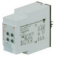
PHASE MONITORING RELAY, SPDT, 240VAC
Manufacturer
CARLO GAVAZZI
Datasheet
1.DPC01DM69.pdf
(6 pages)
Specifications of PPC01DM23
Contact Configuration
SPDT
Phase Type
3 Phase
Power Consumption
9VA
Supply Voltage Max
240VAC
Switching Voltage Max
250VAC
Operating Time Range
0.1s To 30s
Relay Mounting
PCB Socket
Available stocks
Company
Part Number
Manufacturer
Quantity
Price
Company:

Part Number:
PPC01DM23
Manufacturer:
Carlo gavazzi
Quantity:
500


DPC01, PPC01
Mode of Operation
Asymmetry definition.
Asymmetry is an indicator of
the mains quality and it is
defined as the absolute val-
ue of the maximum devia-
tion among the mains volt-
ages, divided by the nominal
voltage of the 3-phase sys-
tem. The definition changes
according to the voltage ref-
erence:
1) in case of measuring
2) in case of measuring
Function/Range/Level/Time Setting
Adjust the input range set-
ting the DIP-switches 3 and
4. Select the desired func-
tion setting the DIP-switches
5 and 6 as shown below. To
Specifications are subject to change without notice (22.11.07)
Example: phase-neutral monitoring
Example: phase-phase monitoring
DPC01
L3
max
max V
phase-phase voltages:
phase-neutral voltages:
|
|
D
Y
V
NOM
PH-N
V’
-V
L1
N
|
max |∆V
max |∆V
L3-N
= V’
PH-N
|
V
|
V
= V
AL
L3-N
∆NOM
|
NOM
0.3
-V’
0. 1
Y
6
2
N’
NOM
L2-N
10
PH-PH
1
V’
PH-N
V
-V’
Y
L2
|
L2-N
NOM
14
L3-N
DELAY 1
3
|
= V
|
|
18
10
22%
30s
x 100
x 100
0.3
max
max V
0. 1
L1-N
6
2
10
= V
1
|
|
D
L2-N
Y
14
DELAY 2
V
3
NOM
PH-N
=V
18
10
22%
30s
-V
/
|
L3-N
= 0
PH-N
Tolerance definition.
Tolerance is another indicator
of the mains quality and it is
definied as the absolute val-
ue of the maximum deviation
of the mains voltages from
the nominal voltage, divided
by the nominal voltage of the
3-phase system. The defini-
tion changes according to
the voltage reference:
1) in case of measuring
2) in case of measuring
access
open the plastic cover using
a
below.
L3
|
Þ
= V
phase-phase voltages:
phase-neutral voltages:
|
L3’
screwdriver
Y
ASY = 0
NOM
-V’
L1’
max |V
max |V
L1
L1-N
N
|
the
= V
|
V
PPC01
V
∆NOM
L2’
Y
NOM
∆NOM
NOM
NOM
-V’
DIP-switches
L2
- V
L2-N
- V
as
|
= V
PH-PH
PH-N
|
Y
NOM
shown
|
|
-V’
x 100
x 100
AL
L3-N
0.3
0. 1
6
2
|
10
1
14
DELAY 1
3
Connected to the 3 phases
(and neutral) DPC01 and
PPC01 operate when all 3
phases are present at the
same time and the phase
sequence is correct. It can
be decided whether to mon-
itor upper and lower voltage
level of each phase or their
asymmetry and tolerance.
Voltage level monitoring:
if one or more phase-phase
or
exceed the upper set level
or drop below the lower set
level, the red LED starts
flashing
respective
releases after the set time
period.
Asymmetry and tolerance
monitoring:
if one or more phase-phase
or
exceed the set levels the red
LED starts flashing 2 Hz and
the respective output relay
releases after the set time
period.
Note: For both functions, if
the
wrong or one phase is lost,
both output relays release
immediately. Only 200 ms
delay occurs. The failure is
indicated by the red LED
flashing 5 Hz during the
alarm condition.
Centre knobs:
Setting of upper ( ) and low-
er ( ) level or setting of
asymmetry (ASY) and toler-
ance (
18
10
22%
30s
0.3
0. 1
6
2
10
1
phase-neutral
phase-neutral
phase
14
DELAY 2
3
18
10
22%
30s
/
) on relative scale.
2
DPC01 400 HZ
output
Hz
sequence
and
voltage
voltage
relay
the
is
Example 1
(Mains monitoring - over and
under phase-phase voltage)
The relay monitors over and
under voltage, phase loss
and
sequence.
Example 2
(Motor monitoring - starting
and operating load -asym-
metry
phase-neutral voltage)
DPC01 and PPC01 ensure
correct starting and operat-
ing conditions. They monitor
the
sequence (correct direction
of the motor rotation) and
asymmetry.
Frequent failures are fuse
blowing and incorrect volt-
age level. In case of fuse
blowing the motor regener-
ates a voltage in the inter-
rupted
detects the failure and reacts
due to excessive imbalance
among the phases.
Lower knobs:
Setting of delay on alarm
times (DELAY 1, DELAY 2)
on absolute scale:
0.1 to 30 s.
AL
0.3
0. 1
6
2
voltage
10
1
and
phase.
14
DELAY 1
3
correct
18
10
22%
30s
0.3
0. 1
6
2
10
tolerance
1
level,
14
DELAY 2
3
The
18
10
22%
30s
/
phase
phase
relay
3
of
Related parts for PPC01DM23
Image
Part Number
Description
Manufacturer
Datasheet
Request
R

Part Number:
Description:
MAGNETIC CYLINDRICAL PROX. SENSOR
Manufacturer:
CARLO GAVAZZI
Datasheet:
Part Number:
Description:
CYLINDRICAL MAGNETIC SENSOR
Manufacturer:
CARLO GAVAZZI
Datasheet:
Part Number:
Description:
MAGNETIC CYLINDRICAL PROX. SENSOR
Manufacturer:
CARLO GAVAZZI
Datasheet:
Part Number:
Description:
Current and Voltage Controls / Current Transformer / 3-Phase
Manufacturer:
Carlo Gavazzi
Datasheet:

Part Number:
Description:
Definite Purpose Contactor
Manufacturer:
CARLO GAVAZZI
Datasheet:
Part Number:
Description:
Definite Purpose Contactor
Manufacturer:
CARLO GAVAZZI
Datasheet: