34.51.7.012.0010 FINDER, 34.51.7.012.0010 Datasheet - Page 4
34.51.7.012.0010
Manufacturer Part Number
34.51.7.012.0010
Description
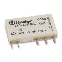
POWER RELAY, SPDT-CO, 12VDC, 6A PC BOARD
Manufacturer
FINDER
Datasheet
1.34.51.7.012.0010.pdf
(8 pages)
Specifications of 34.51.7.012.0010
Relay Type
PCB
Coil Voltage Vdc Nom
12V
Contact Current Max
6A
Contact Voltage Ac Nom
250V
Coil Resistance
840ohm
Contact Configuration
SPCO
Coil Type
DC
Coil Current
14.2mA
Lead Free Status / RoHS Status
Lead free / RoHS Compliant
Available stocks
Company
Part Number
Manufacturer
Quantity
Price
Company:

Part Number:
34.51.7.012.0010
Manufacturer:
WALSIN
Quantity:
600 000


34
Technical data
F 34 - Electrical life (AC) v contact current
DC coil data
10
Contact specification
Coil specifications
Insulation
Insulation according to EN 61810-1 ed. 2
Insulation between coil and contacts (1.2/50 µs)
Dielectric strength between open contacts
Conducted disturbance immunity
Burst (5...50)ns, 5 kHz, on A1 - A2
Surge (1.2/50 µs) on A1 - A2 (differential mode)
Other data
Bounce time: NO/NC
Vibration resistance (5…55)Hz, max. ± 1 mm: NO/NC
Shock resistance
Power lost to the environment
Recommended distance between relays mounted on PCB
Nominal
voltage
U
12
24
48
60
V
N
5
10
10
10
10
7
6
5
4
0
7.005
7.012
7.024
7.048
7.060
code
Coil
2
Operating range
16.8
33.6
42
U
3.5
8.4
V
min
Resistive load - cosϕ = 1
Inductive load - cosϕ = 0.4
4
U
18
36
72
90
max
V
7.5
Resistance Rated coil
insulation rated voltage
rated impulse withstand voltage
pollution degree
overvoltage category
without contact current
with rated current
12,300
19,700
3,350
Ω
6
R
130
840
Electromechanical relay
consumption
I at U
mA
38.4
14.2
7.1
3.9
3
(A)
8
N
• When switching a resistive load (DC1) having voltage and current
• In the case of DC13 loads, the connection of a diode in parallel with
R 34 - DC coil operating range v ambient temperature
1 - Max. permitted coil voltage.
2 - Min. pick-up voltage with coil at ambient temperature.
H 34 - Maximum DC1 breaking capacity
values under the curve, an electrical life of ≥ 60·10
the load will permit a similar electrical life as for a DC1 load.
Note: the release time for the load will be increased.
U
U
N
V AC
0.2
0.1
2.0
1.5
1.0
0.5
g/g
g/g
20
10
mm
ms
6
kV
kV
W
W
4
2
1
34 Series - Ultra-Slim PCB relays
20
V
-20
250
4
3
III
6
1,000
EN 61000-4-4
EN 61000-4-5
1/6
10/5
20/14
0.2
0.5
≥ 5
60
0
20
100
DC voltage (V)
40
140
400
4
2
III
level 4 (4 kV)
level 3 (2 kV)
60
3
180
can be expected.
2
1
(°C)
80
220
Related parts for 34.51.7.012.0010
Image
Part Number
Description
Manufacturer
Datasheet
Request
R

Part Number:
Description:
JUMPER LINK, 20WAY
Manufacturer:
FINDER
Datasheet:


Part Number:
Description:
INTERFACE RELAY, SPDT-CO, 24VAC/DC
Manufacturer:
FINDER
Datasheet:
Part Number:
Description:
INTERFACE RELAY, SPDT-CO, 24VDC
Manufacturer:
FINDER
Datasheet:

Part Number:
Description:
RELAY, SCREW TERM, 6A, 12VAC/DC
Manufacturer:
FINDER
Datasheet:
Part Number:
Description:
RELAY, SCREW TERM, 6A, 48VAC/DC
Manufacturer:
FINDER
Datasheet:
Part Number:
Description:
RELAY, SCREW TERM, 6A, 125VAC/DC
Manufacturer:
FINDER
Datasheet:
Part Number:
Description:
RELAY, SCREW TERM, 6A, 240VAC/DC
Manufacturer:
FINDER
Datasheet:
Part Number:
Description:
RELAY, SCREW TERM, 6A, 6VDC
Manufacturer:
FINDER
Datasheet:
Part Number:
Description:
RELAY, SCREW TERM, 6A, 12VDC
Manufacturer:
FINDER
Datasheet:
Part Number:
Description:
RELAY, SCRW TER, DPDT, 8A, 24VAC/DC
Manufacturer:
FINDER
Datasheet:
Part Number:
Description:
RELAY, SCREW TERM, DPDT, 8A, 12VDC
Manufacturer:
FINDER
Datasheet:
Part Number:
Description:
RELAY, SCREW TERM, DPDT, 8A, 24VDC
Manufacturer:
FINDER
Datasheet:

Part Number:
Description:
RELAY, SCREWLESS, 6A, 24VDC
Manufacturer:
FINDER
Datasheet: