RJ1P23I50E CARLO GAVAZZI, RJ1P23I50E Datasheet - Page 4
RJ1P23I50E
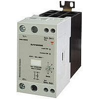
Manufacturer Part Number
RJ1P23I50E
Description
SSR, DIN RAIL MOUNT, 265VAC, 50A
Manufacturer
CARLO GAVAZZI
Datasheet
1.RJ1P23I50E.pdf
(8 pages)
Specifications of RJ1P23I50E
Operating Voltage Range
90VAC To 265VAC
Peak Surge Current
1.9kA
Contact Configuration
SPST
Load Current
50A
Switching Mode
Analog
Relay Terminals
Cage Clamp
Output Voltage Min
90V
Input Current Max
20mA


4
MODE 1: The Phase Angle
switching mode works in
accordance with the phase
angle control principle, i.e. the
output switching point in the
AC sine wave depends on the
signal level applied at the
input. The relay switches off
everytime the output current
crosses zero.
MODE 2: The Distributed
mode provides a number of
full cycles, evenly distributed
over a fixed period of 1.28s @
50Hz (1.07s @ 60Hz), depend-
ing on the control input.
RJ1P
Operation
Terminal Layout
Transfer characteristics
Output power as a function of control input
Dissipation Curve
Current (mA)
Control
W
12
16
20
4
8
50
40
30
20
10
0
0
10
Voltage (VDC)
20
Control
AACrms
2.5
7.5
10
0
5
30
MODE 3, 4, 5: The Burst
Switching mode generates a
number of full cycles, depend-
ing on the control input over
fixed periods of 1s, 3s or 10s
for MODES 3, 4 and 5 respec-
tively.
Modes 2, 3, 4 and 5 use the
zero switching principle, thus
ensuring a reduced level of
radiated and wire-conducted
noise. The Distributed and
Burst Switching modes are not
recommended for light control
due to light-flickering.
30A
40
50
50A
Power (%)
Output
60
25
50
75
99
0
LED INDICATION
The top RED LED indicates
the load status. It goes ON
whenever the load is activat-
ed, and in the RJ1P…P..O
models this led is used to indi-
cate an over temperature
alarm. The Green LED gives
indication of the status of the
control input.
Upon application of control
current (for the RJ1P..I..) to ter-
minals A1 – A3, the Green LED
will be dimly lit, with its inten-
sity
increase in control current.
Mode Selection
MODE 1
MODE 2
MODE 3
MODE 4
MODE 5
Specifications are subject to change without notice (05.10.2007)
increasing
Phase Angle Switching
Distributed Control
Burst Switching (1 sec. period)
Burst Switching (3 sec. period)
Burst Switching (10 sec. period)
with
an
For the RJ1P..V.. the Green
LED will be ON (flickering)
upon application of the supply
voltage to terminals A3 – A4.
In RJ1P..VE only, terminals A3
and A2 are shorted. Once a
control voltage is applied to
terminals A1 – A3, the Green
LED will be fully ON, if greater
than a threshold voltage
(approx 0.5V). Note that the
first time the device (voltage
control version) is to be acti-
vated, the mains voltage has
to be present for the Green
LED to indicate the control
status.
Related parts for RJ1P23I50E
Image
Part Number
Description
Manufacturer
Datasheet
Request
R

Part Number:
Description:
MAGNETIC CYLINDRICAL PROX. SENSOR
Manufacturer:
CARLO GAVAZZI
Datasheet:
Part Number:
Description:
CYLINDRICAL MAGNETIC SENSOR
Manufacturer:
CARLO GAVAZZI
Datasheet:
Part Number:
Description:
MAGNETIC CYLINDRICAL PROX. SENSOR
Manufacturer:
CARLO GAVAZZI
Datasheet:
Part Number:
Description:
Current and Voltage Controls / Current Transformer / 3-Phase
Manufacturer:
Carlo Gavazzi
Datasheet:

Part Number:
Description:
Definite Purpose Contactor
Manufacturer:
CARLO GAVAZZI
Datasheet:
Part Number:
Description:
Definite Purpose Contactor
Manufacturer:
CARLO GAVAZZI
Datasheet: