RSSAN-90A IDEC, RSSAN-90A Datasheet - Page 3
RSSAN-90A
Manufacturer Part Number
RSSAN-90A
Description
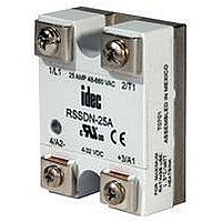
SSR, DIN/PANEL MOUNT, 660VAC, 280VAC 90A
Manufacturer
IDEC
Datasheet
1.RSSAN-10A.pdf
(4 pages)
Specifications of RSSAN-90A
Control Voltage Range
90VAC To 280VAC
Operating Voltage Range
48VAC To 660VAC
Load Current
90A
Isolation Voltage
4000Vrms
Control Voltage Type
AC
Relay Terminals
Screw
Lead Free Status / RoHS Status
Lead free / RoHS Compliant


E
RSS Series
E-38
Environment
Do not install SSRs near sources of excessive heat. Make sure applications are dry and well ventilated.
If SSRs must be installed in an environment subject to high temperatures or poor ventilation, or if SSRs are mounted collectively, reduce the load current so that it
does not approach the ambient temperature-load current recommendation. (See the Temperature Derating Curves on the following page.)
When SSRs are used with inductive loads, suppress the inrush current to half of the peak surge current.
Heat Sinks
Heat sinks are recommended for 10, 25, 50, 75, and 90 amp rated solid state relays depending on ambient temperature and mounting position. The recommended
heat sink dimensions and material are shown in the table:
Using a thermal compound between the base of the SSR and the heat sink for heat dissipation is recommended.
Wiring
Locate SSRs as far from motor leads as possible to prevent malfunction from induced current.
Use shielded wires for input leads when they are exposed to a source of induced current.
Mounting
Provide sufficient ventilation.
Use #6 – 32 screws, flat washers, and lock washers to secure mounting on heat sinks.
Vertical mounting is recommended to allow air to flow unimpeded. Horizontal or inverted mounting is possible, but the SSR must be derated according to the der-
ating curves on the following page.
Additional Information
Do not exceed the load voltage and current specifications.
A small-capacity load may not turn off due to the leakage current present after the SSR has turned off. If this is the case, use a resistor in parallel with the load to
shunt the leakage current.
Observe the polarity of input terminals. Failure to do so may cause damage to the SSR.
When the SSR output is subjected to a higher than rated voltage, a varistor or other element should be connected to the output terminals to absorb the over-volt-
age.
When the input signal contains a ripple voltage, the lowest ripple amplitude should exceed the minimum pick-up voltage of 4V.
Over 4V
Output Rating
0V
10A
25A
25A
50A
75A
90A
Dimensions
12" x 12" x 1/8"
12" x 12" x 1/8" (DC/AC)
15" x 15" x 1/8" (AC/AC)
15" x 15" x 1/8"
17" x 17" x 1/8"
17" x 17" x 1/8"
www.idec.com
Lowest Voltage
Material
Aluminum (black anodized)
Aluminum (black anodized)
Aluminum (black anodized)
Aluminum (black anodized)
Aluminum (black anodized)
Aluminum (black anodized)
Technical Notes
USA: (800) 262-IDEC or (408) 747-0550, Canada: (888) 317-IDEC
Relays
Related parts for RSSAN-90A
Image
Part Number
Description
Manufacturer
Datasheet
Request
R

Part Number:
Description:
SSR, DIN/PANEL MOUNT, 660VAC, 280VAC 10A
Manufacturer:
IDEC
Datasheet:
Part Number:
Description:
SSR, DIN/PANEL MOUNT, 660VAC, 280VAC 50A
Manufacturer:
IDEC
Datasheet:
Part Number:
Description:
SSR, DIN/PANEL MOUNT, 660VAC, 280VAC 75A
Manufacturer:
IDEC
Datasheet:

Part Number:
Description:
Relay; SSR; Zero-Switching; SPST-NO; Cur-Rtg 25A; Ctrl-V 90-280AC; Vol-Rtg 48-660AC
Manufacturer:
IDEC Corporation
Datasheet:
Part Number:
Description:
Cable; Between IDEC MicroSmart (port 1 or 2) and HG2F/3F/4F; 5 ft.
Manufacturer:
IDEC Corporation
Datasheet:
Part Number:
Description:
Cable; Between IDEC Micro^3C/ONC/MicroSmart (port 2) PLCs and HG2F/3F/4F; 5 ft.
Manufacturer:
IDEC Corporation
Datasheet:
Part Number:
Description:
Angled Key for Idec HS6B Safety Switch
Manufacturer:
IDEC Corporation
Datasheet:
Part Number:
Description:
Accessory, L-Shaped Key for Idec HS5B and HS5E Safety Switch
Manufacturer:
IDEC Corporation
Datasheet:
Part Number:
Description:
Accessory, Straight Key for Idec HS5B and HS5E Safety Switch
Manufacturer:
IDEC Corporation
Datasheet:
Part Number:
Description:
Straight Key for Idec HS6B Safety Switch
Manufacturer:
IDEC Corporation
Datasheet:
Part Number:
Description:
ECONOLINE - DC/DC - CONVERTER
Manufacturer:
Recom International Power
Datasheet:
Part Number:
Description:
ECONOLINE - DC/DC - CONVERTER
Manufacturer:
Recom International Power
Part Number:
Description:
ECONOLINE - DC/DC - CONVERTER
Manufacturer:
Recom International Power
Part Number:
Description:
1 Watt SMD Single & Dual Output
Manufacturer:
RECOM [Recom International Power]
Datasheet:
Part Number:
Description:
ECONOLINE - DC/DC - CONVERTER
Manufacturer:
RECOM [Recom International Power]
Datasheet: