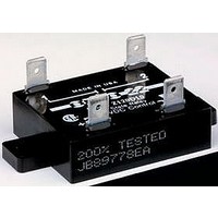
P120D2 OPTO 22, P120D2 Datasheet - Page 16

P120D2
Manufacturer Part Number
P120D2
Description
SSR, PCB MOUNT, 140VAC, 24VDC, 2A
Manufacturer
OPTO 22
Specifications of P120D2
Control Voltage Type
DC
Input Voltage
3VDC To 24VDC
Load Current
2A
Load Voltage Range
12VAC To 140VAC
Switching Mode
Zero Cross
Relay Terminals
Through Hole
Load Voltage Max
140VAC
Brand/series
P Series
Current, Rating
2 A
Function
General Purpose
Relay Type
Solid State
Voltage, Control
120 VAC
Control Voltage Max
32V
Rohs Compliant
Yes
Lead Free Status / RoHS Status
Lead free / RoHS Compliant
PAGE
16
Sample Calculation 2
240-volt,18-amp load, 25 °C ambient air temperature
Model: 240D45
See the last two columns of the table on
the bottom of the table.
Dissipation: 0.9 watts/amp
Thermal resistance: 0.67 °C/watt
Maximum junction temperature: 110 °C
The calculation would be as follows:
Duty Cycle Calculation
When solid-state relays are operated in an on/off mode, it may be advantageous to calculate the RMS value of the current through
the SSR for heat sinking or determining the proper current rating of the SSR for the given application.
Opto 22 • 43044 Business Park Drive • Temecula, CA 92590-3614 • www.opto22.com
© 2006–2011 Opto 22. All rights reserved. Dimensions and specifications are subject to change. Brand or product names used herein are trademarks or registered trademarks of their respective companies or organizations.
800-321-6786 • 951-695-3000 • FAX 951-695-3095 • sales@opto22.com •
I
T
T
I
RMS
ON
1
2
= Time current is on
= Time current is off
= RMS value of load current during on period
= RMS value of load or SSR
page 4
for thermal resistance and dissipation values for the 240D45. Also, see the note at
I
RMS
800-835-6786 • 951-695-3080 • FAX 951-695-3017 • support@opto22.com
=
(I
This calculation indicates that you should
select a heat sink with a thermal resistance
of less than 4.6 °C/watt.
T
ON
1
)
+ T
2
x T
2
1
Solid-State Relays


