SCR1100-D04 VTI Technologies, SCR1100-D04 Datasheet - Page 8
SCR1100-D04
Manufacturer Part Number
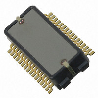
SCR1100-D04
Description
SENSOR GYRO 300DEG SNGL AXIS SPI
Manufacturer
VTI Technologies
Datasheet
1.SCR1100-D04.pdf
(21 pages)
Specifications of SCR1100-D04
New! Us2012 Catalog Page
Single Axis Gyroscopes
Range °/s
±300°/s
Sensitivity
18LSB/°/s
Typical Bandwidth
50Hz
Voltage - Supply
3 V ~ 3.6 V, 4.75 V ~ 5.25 V
Current - Supply
20mA, 26mA
Output Type
Analog, Digital
Operating Temperature
-40°C ~ 125°C
Package / Case
32-SOP
Lead Free Status / RoHS Status
Lead free / RoHS Compliant
Other names
551-1077-2


3
3.1 Power-up Sequence
Table 5. SCR1100 gyroscope power-up sequence.
3.2 Reset
4
4.1 SPI Interfaces
4.1.1 SPI Transfer
VTI Technologies Oy
www.vti.fi
Procedure
Set V
Wait 10ms
Set V
Wait 800 ms
Read Status register (08h) two times
Reset and Power Up
Component Interfacing
DVDD_G
AVDD_G
V=3.0...3.6V
V=4.75...5.25V
After the start-up the angular rate and acceleration data is immediately available through SPI
registers. There is no need to initialize the gyroscope or accelerometer before starting to use it. If
the application requires monitoring operation correctness there are several options available to
monitor the status.
To ensure correct ASIC start up please connect the digital supply voltage V
analog supply voltage V
twice to clear error flags. Angular rate data is available immediately so no start up command
sequence is required if error flags are not used.
SCR1100 can be reset by writing 0x04 in to IC Identification register (address 07h) or with external
active low reset pin (EXTRESN_G). Power supplies should be within the specified range before the
reset pin can be released.
SCR1100 sensor SPI interface is a digital 4 wire interface where SCR1100 always operate as
slave devices in the master-slave operation mode.
SCR1100 Angular rate sensor ASIC SPI interface:
The SPI transfer is based on a 16-bit protocol. Figure 5 shows an example of a single 16-bit data
transmission. Each output data/status-bits are shifted out on the falling edge of SCK (MISO line).
Each bit is sampled on the rising edge of SCK (MOSI line).
Figure 4. SCR1100 angular rate sensor 16-bit data transmission.
MOSI_G
MISO_G
SCK_G
CSN_G
AVDD_G
Doc.Nr. 82 1226 00 A
Subject to changes
Functions
Acknowledge error flags after start up
master out slave in
master in slave out
serial clock
chip select (low active)
(5.0V) to the gyro ASIC. After power up please read Status register
Check
µP → ASIC
ASIC → µP
µP → ASIC
µP → ASIC
DVDD_G
(3.3V) before the
SCR1100-D04
Rev. 0.3
8/21
Related parts for SCR1100-D04
Image
Part Number
Description
Manufacturer
Datasheet
Request
R

Part Number:
Description:
Manufacturer:
Samtec Inc
Datasheet:
Part Number:
Description:
Manufacturer:
Samtec Inc
Datasheet:
Part Number:
Description:
SEALED CIRCULAR POWER RECEPTACLE
Manufacturer:
Samtec Inc

Part Number:
Description:
ACCELEROMETER SGL 1.7G DIL8 SMD
Manufacturer:
VTI Technologies
Datasheet:

Part Number:
Description:
VTI Automotive Digital Accelerometer Platform
Manufacturer:
VTI [VTI technologies]
Datasheet:

Part Number:
Description:
BOARD PWB ACCEL 3-AXIS SPI/I2C
Manufacturer:
VTI Technologies
Datasheet:

Part Number:
Description:
EVAL BOARD ACCELEROMETER Y-AXIS
Manufacturer:
VTI Technologies
Datasheet:

Part Number:
Description:
EVAL BOARD INCLINOMETER Y-AXIS
Manufacturer:
VTI Technologies
Datasheet:
Part Number:
Description:
ACCELEROMETER SGL 1.7G DIL8 SMD
Manufacturer:
VTI Technologies
Datasheet:
Part Number:
Description:
VTI Automotive Digital Accelerometer Platform
Manufacturer:
VTI [VTI technologies]
Datasheet:
Part Number:
Description:
Accelerometer
Manufacturer:
VTI [VTI technologies]
Datasheet:
Part Number:
Description:
Stand Alone Inclinometer
Manufacturer:
VTI [VTI technologies]
Datasheet:
Part Number:
Description:
3-axis accelerometer
Manufacturer:
VTI [VTI technologies]
Datasheet: