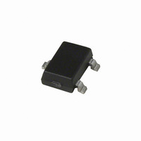
A1102LLHLT-T Allegro Microsystems Inc, A1102LLHLT-T Datasheet

A1102LLHLT-T
Specifications of A1102LLHLT-T
Available stocks
Related parts for A1102LLHLT-T
A1102LLHLT-T Summary of contents
Page 1
Features and Benefits ▪ Continuous-time operation ▫ Fast power-on time ▫ Low noise ▪ Stable operation over full operating temperature range ▪ Reverse battery protection ▪ Solid-state reliability ▪ Factory-programmed at end-of-line for optimum performance ▪ Robust EMC performance ▪ ...
Page 2
... Bulk, 500 pieces/bag A1101LLHLT-T 7-in. reel, 3000 pieces/reel A1101LUA-T Bulk, 500 pieces/bag A1102ELHLT-T 7-in. reel, 3000 pieces/reel A1102EUA-T Bulk, 500 pieces/bag A1102LLHLT-T 7-in. reel, 3000 pieces/reel A1102LUA-T Bulk, 500 pieces/bag A1103ELHLT-T 7-in. reel, 3000 pieces/reel A1103LLHLT-T 7-in. reel, 3000 pieces/reel A1103LUA-T ...
Page 3
A1101, A1102, A1103, A1104, and A1106 ELECTRICAL OPERATING CHARACTERISTICS over full operating voltage and ambient temperature ranges, unless otherwise noted Characteristic Symbol 1 Supply Voltage V Output Leakage Current I OUTOFF Output On Voltage V OUT(SAT) Power-On Time 2 3 ...
Page 4
A1101, A1102, A1103, A1104, and A1106 MAGNETIC OPERATING CHARACTERISTICS Characteristic Symbol Operate Point B Release Point B Hysteresis B 1 Magnetic flux density indicated as a negative value for north-polarity magnetic fields, and as a positive value for ...
Page 5
A1101, A1102, A1103, A1104, and A1106 Characteristic Package Thermal Resistance Continuous-Time Switch Family Symbol Package LH, 1-layer PCB with copper limited to solder pads Package LH, 2-layer PCB with 0.463 in. R θJA side connected by thermal vias Package UA, ...
Page 6
A1101, A1102, A1103, A1104, and A1106 Supply Current (On) versus Ambient Temperature (A1101/02/03/04/06) 8.0 7.0 6.0 5.0 4.0 3.0 2.0 1.0 0 – (°C) A Supply Current (Off) versus Ambient Temperature (A1101/02/03/04/06) 8.0 7.0 6.0 5.0 4.0 ...
Page 7
A1101, A1102, A1103, A1104, and A1106 OPERATION The output of these devices switches low (turns on) when a magnetic field (south polarity) perpendicular to the Hall ele- ment exceeds the operate point threshold, B the output is capable of sinking ...
Page 8
A1101, A1102, A1103, A1104, and A1106 ADDITIONAL APPLICATIONS INFORMATION Extensive applications information for Hall-effect devices is available in: • Hall-Effect IC Applications Guide, Application Note 27701 • Hall-Effect Devices: Gluing, Potting, Encapsulating, Lead Welding and Lead Forming, Application Note 27703.1 ...
Page 9
A1101, A1102, A1103, A1104, and A1106 Power Derating The device must be operated below the maximum junction temperature of the device Under certain combinations of J(max) peak conditions, reliable operation may require derating sup- plied power or improving ...
Page 10
A1101, A1102, A1103, A1104, and A1106 +0.12 2.98 –0.08 3 +0.10 2.90 –0. 10° REF 0.95 BSC For Reference Only; not for tooling use (reference dwg. 802840) Dimensions in millimeters Dimensions exclusive of mold flash, gate burrs, and ...
Page 11
A1101, A1102, A1103, A1104, and A1106 4.09 45° +0.08 3.02 –0.05 2.16 MAX 0.51 REF 1 15.75 ±0.51 +0.05 0.43 –0.07 Copyright ©2006-2009, Allegro MicroSystems, Inc. Allegro MicroSystems, Inc. reserves the right to make, from time to time, such de ...


