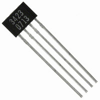
A3423LK-T Allegro Microsystems Inc, A3423LK-T Datasheet - Page 7

A3423LK-T
Manufacturer Part Number
A3423LK-T
Description
IC DIRECTION SENSOR 2CH 4-SIP
Manufacturer
Allegro Microsystems Inc
Type
Special Purposer
Specifications of A3423LK-T
Package / Case
4-SIP
Sensing Range
55G Trip, -55G Release
Voltage - Supply
3.8 V ~ 24 V
Current - Supply
14mA
Current - Output (max)
30mA
Output Type
Digital, Open Collector
Features
Regulated Voltage
Operating Temperature
-40°C ~ 150°C
Output Current
30mA
Sensor Case Style
SIP
No. Of Pins
4
Supply Voltage Range
3.8V To 24V
Operating Temperature Range
-40°C To +150°C
Base Number
3423
Supply Voltage
RoHS Compliant
Svhc
No SVHC (15-Dec-2010)
Rohs Compliant
Yes
Lead Free Status / RoHS Status
Lead free / RoHS Compliant
Other names
620-1207
A3423
The integrated circuit contains an internal voltage regulator that
powers the Hall elements and both the analog and digital cir-
cuitry. This regulator allows operation over a wide supply voltage
range and provides some immunity to supply noise. The device
also contains logic circuitry that decodes the direction of rotation
of the ring magnet.
Quadrature/Direction Detection
outputs representing the speed and direction of the magnetic
field across the face of the package. For the direction signal to be
appropriately updated, a quadrature relationship must be main-
tained between the target magnetic pole width, the pitch between
the two Hall elements (E1 and E2) in the device, and, to a lesser
extent, the magnetic switchpoints.
For optimal design, the device should be actuated by a ring
magnet that presents to the front of the device a field with a pole
width two times the Hall element-to-element spacing. This will
produce a sinusoidal magnetic field whose period (denoted as Τ)
is then four times the element-to-element spacing. A quadrature
relationship can also be maintained for a ring magnet with fields
having a period that satisfies the relationship:
where n is any odd integer. Therefore, ring magnets with pole-
pair spacing equal to 6.52 mm (n = 1), 2.17 mm (n = 3), 1.3 mm
(n = 5), and so forth, are permitted.
(OUTA XOR
OUTB
OUTA
OUTB)
SPD
DIR
+B
–B
+B
–B
0
0
Target changes direction of rotation
nΤ/4 = 1.63 mm ,
Figure 1
Dual Channel Hall Effect Direction Detection Sensor IC
Internal logic circuitry provides
t
d
Functional Description
The response of the device to the magnetic field produced by a
rotating ring magnet is shown in the Performance Characteristics
section. Note the phase shift between the two integrated Hall ele-
ments.
Outputs
direction (DIR pin), E1 element output (OUTA pin), E2 element
output (OUTB pin), and target speed (SPD pin).
DIR provides the direction output of the device and is defined
as off (high) for targets moving in the direction from E1 to E2
and on (low) for the direction E2 to E1. SPD provides an XORed
output of the two Hall elements (see figure 1). Because of inter-
nal delays, DIR is always updated before SPD and is updated at
every transition of OUTA and OUTB (internal) allowing the use
of up-down counters without the loss of pulses.
Power-on State
vide an off (high) state for all the outputs. If any of the channels
is subjected to a field greater than B
accordingly, and the outputs will switch to the expected state.
Power-on Time
when the supply voltage reaches the device supply minimum
until the device output becomes valid (see figure 2).
The device provides up to four saturated outputs: target
This characteristic, t
At power on, the logic circuitry is reset to pro-
115 Northeast Cutoff
1.508.853.5000; www.allegromicro.com
Allegro MicroSystems, Inc.
Worcester, Massachusetts 01615-0036 U.S.A.
Figure 2
OP
ON
, the internal logic will set
, is the elapsed time from
6


