ATS612LSB Allegro Microsystems Inc, ATS612LSB Datasheet - Page 11
ATS612LSB
Manufacturer Part Number
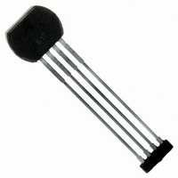
ATS612LSB
Description
IC SENSOR GEAR TOOTH 4LEAD
Manufacturer
Allegro Microsystems Inc
Type
Special Purposer
Datasheet
1.ATS612LSB.pdf
(17 pages)
Specifications of ATS612LSB
Sensing Range
*
Voltage - Supply
3.6 V ~ 24 V
Current - Supply
15mA
Current - Output (max)
55mA
Output Type
Digital, Open Collector
Features
Gear Tooth Type
Operating Temperature
-40°C ~ 150°C
Package / Case
4-SIP
Lead Free Status / RoHS Status
Contains lead / RoHS non-compliant
Available stocks
Company
Part Number
Manufacturer
Quantity
Price
Company:

Part Number:
ATS612LSB
Manufacturer:
ATMEL
Quantity:
201


Peak-Detecting vs. AC-Coupled Filters. High-pass
filtering (normal ac coupling) is a commonly used tech-
nique for eliminating circuit offsets. AC coupling has errors
at power on because the filter circuit needs to hold the
circuit zero value even though the circuit may power on
over a large signal. Such filter techniques can only
perform properly after the filter has been allowed to settle,
which is typically greater than one second. Also,
high-pass filter solutions cannot easily track rapidly
changing baselines such as those caused by eccentrici-
ties. Peak detection switches on the change in slope of
the signal and is baseline independent at power up and
during running.
Peak Detecting vs. Zero-Crossing Reference. The
usual differential zero-crossing sensors are susceptible to
false switching due to off-center and tilted installations,
which result in a shift in baseline that changes with air gap.
The track-and-hold peak-detection technique ignores
baseline shifts versus air gaps and provides increased
immunity to false switching. In addition, using
track-and-hold peak-detecting techniques, increased air
gap capabilities can be expected because a peak detector
utilizes the entire peak-to-peak signal range as compared
10
ATS612LSB
DYNAMIC, SELF-CALIBRATING, PEAK-DETECTING,
DIFFERENTIAL HALL-EFFECT GEAR-TOOTH SENSOR IC
DEVICE DESCRIPTION — Continued
115 Northeast Cutoff, Box 15036
Worcester, Massachusetts 01615-0036 (508) 853-5000
to zero-crossing detectors that switch on one-half the
peak-to-peak signal.
NOTE — “Baseline” refers to the zero-gauss differential
where each Hall-effect element is subject to the same
magnetic field strength.
Power-On Operation. The device will power on in the
OFF state (output high) irrespective of the magnetic field
condition. The power-up time of the circuit is no greater
than 500 µs. The circuit is then ready to accurately detect
the first target edge that results in a HIGH-to-LOW transi-
tion.
Under-Voltage Lockout. When the supply voltage is
below the minimum operating voltage (V
device is OFF and stays OFF irrespective of the state of
the magnetic field. This prevents false signals, which may
be caused by under-voltage conditions (especially during
turn on), from appearing at the output.
Output. The device output is an open-collector stage
capable of sinking up to 20mA. An external pull-up
(resistor) to a supply voltage of not more than 24V must
be supplied.
CC(UV)
), the
Related parts for ATS612LSB
Image
Part Number
Description
Manufacturer
Datasheet
Request
R

Part Number:
Description:
IC, HALL EFFECT SENSOR, Linear, SOIC-8
Manufacturer:
Allegro Microsystems Inc
Datasheet:
Part Number:
Description:
IC, HALL EFFECT SENSOR, Linear, SOIC-8
Manufacturer:
Allegro Microsystems Inc
Datasheet:
Part Number:
Description:
IC, HALL EFFECT SENSOR, Linear, SOIC-8
Manufacturer:
Allegro Microsystems Inc
Datasheet:

Part Number:
Description:
IC SWITCH INTERFACE 2CHAN 8-SOIC
Manufacturer:
Allegro Microsystems Inc
Datasheet:

Part Number:
Description:
IC SMOKE DETECTOR ION 16-DIP
Manufacturer:
Allegro Microsystems Inc
Datasheet:
Part Number:
Description:
IC SMOKE DETECTOR ION 16-DIP
Manufacturer:
Allegro Microsystems Inc
Datasheet:
Part Number:
Description:
IC SMOKE DETECTOR ION 16-DIP
Manufacturer:
Allegro Microsystems Inc
Datasheet:
Part Number:
Description:
IC SMOKE DETECTOR PHOTO 16-DIP
Manufacturer:
Allegro Microsystems Inc
Datasheet:
Part Number:
Description:
IC SMOKE DETECTOR ION 16-DIP
Manufacturer:
Allegro Microsystems Inc
Datasheet:
Part Number:
Description:
IC SMOKE DETECTOR PHOTO 16-DIP
Manufacturer:
Allegro Microsystems Inc
Datasheet:
Part Number:
Description:
IC SMOKE DETECTOR PHOTO 16-DIP
Manufacturer:
Allegro Microsystems Inc
Datasheet:
Part Number:
Description:
IC SMOKE DETECTOR ION 16-DIP
Manufacturer:
Allegro Microsystems Inc
Datasheet:
Part Number:
Description:
IC SMOKE DETECTOR PHOTO 16-SOIC
Manufacturer:
Allegro Microsystems Inc
Datasheet:

Part Number:
Description:
IC LED DRIVER HIGH BRIGHT 16-QFN
Manufacturer:
Allegro Microsystems Inc
Datasheet:

Part Number:
Description:
IC LED DRIVER AUTOMOTIVE 8-SOIC
Manufacturer:
Allegro Microsystems Inc
Datasheet: