ATS625LSGTN Allegro Microsystems Inc, ATS625LSGTN Datasheet - Page 14
ATS625LSGTN
Manufacturer Part Number
ATS625LSGTN
Description
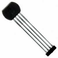
IC SENSOR GEAR TOOTH 4-SIP
Manufacturer
Allegro Microsystems Inc
Type
Special Purposer
Datasheet
1.ATS625LSGTN.pdf
(21 pages)
Specifications of ATS625LSGTN
Sensing Range
60% Trip, 40% Release
Voltage - Supply
4 V ~ 24 V
Current - Supply
14mA
Current - Output (max)
10mA
Output Type
Digital, Open Collector
Features
Gear Tooth Type
Operating Temperature
-40°C ~ 150°C
Package / Case
4-SIP
Lead Free Status / RoHS Status
Contains lead / RoHS non-compliant
Available stocks
Company
Part Number
Manufacturer
Quantity
Price


ATS625LSG
SWITCHPOINTS
Switchpoints in the ATS625 are a percentage of the amplitude of
the signal, V
the actual switching levels are determined dynamically. Two
DACs track the peaks of V
The switching thresholds are established at 40% and 60% of the
values held in the two DACs. The proximity of the thresholds
near the 50% level ensures the most accurate and consistent
switching, because it is where the slope of V
least affected by air gap variation.
The low hysteresis, 20%, provides high performance over vari-
ous air gaps and immunity to false switching on noise, vibration,
backlash, or other transient events.
Figure 8 graphically demonstrates the establishment of the
switching threshold levels. Because the thresholds are established
dynamically as a percentage of the peak-to-peak signal, the effect
of a baseline shift is minimized. As a result, the effects of offsets
induced by tilted or off-center installation are minimized.
UPDATE
The ATS625 incorporates an algorithm that continuously moni-
tors the system and updates the switching thresholds accordingly.
The switchpoint for each edge is determined by the signal result-
Figure 8. Switchpoint Relationship to Thresholds.The device switches
when V
corresponding direction: increasing for a B
for a B
RP
PROC
switchpoint.
passes a threshold level, B
100
60
40
PROC
V+
0
Switching Threshold Levels
, after normalization with AGC. In operation,
Off
At Constant V
PROC
On
(see the Update subsection).
PROC
Off
OP
OP
or B
Level
switchpoint, and decreasing
RP
On
, while changing in the
PROC
True Zero-Speed Low-Jitter High Accuracy
is steepest and
B OP
B RP
ing from the previous two edges. Because variations are tracked
in real time, the device has high immunity to target run-out and
retains excellent accuracy and functionality in the presence of
both run-out and transient mechanical events. Figure 9 shows
how the device uses historical data to provide the switching
threshold for a given edge.
Figure 9. Switchpoint Determination. The two previous V
used to determine the next threshold level: panel A, operate point, and
panel B, release point.
Dynamic B
Dynamic B
100
100
60
40
V+
V+
0
0
Gear Tooth Sensor IC
OP
RP
Threshold Determination
Threshold Determination
115 Northeast Cutoff
1.508.853.5000; www.allegromicro.com
Allegro MicroSystems, Inc.
Worcester, Massachusetts 01615-0036 U.S.A.
On
(A)
(B)
B OP
Off
Off
B RP
On
PROC
peaks are
14
Related parts for ATS625LSGTN
Image
Part Number
Description
Manufacturer
Datasheet
Request
R

Part Number:
Description:
IC, HALL EFFECT SENSOR, Linear, SOIC-8
Manufacturer:
Allegro Microsystems Inc
Datasheet:
Part Number:
Description:
IC, HALL EFFECT SENSOR, Linear, SOIC-8
Manufacturer:
Allegro Microsystems Inc
Datasheet:
Part Number:
Description:
IC, HALL EFFECT SENSOR, Linear, SOIC-8
Manufacturer:
Allegro Microsystems Inc
Datasheet:

Part Number:
Description:
IC SWITCH INTERFACE 2CHAN 8-SOIC
Manufacturer:
Allegro Microsystems Inc
Datasheet:

Part Number:
Description:
IC SMOKE DETECTOR ION 16-DIP
Manufacturer:
Allegro Microsystems Inc
Datasheet:
Part Number:
Description:
IC SMOKE DETECTOR ION 16-DIP
Manufacturer:
Allegro Microsystems Inc
Datasheet:
Part Number:
Description:
IC SMOKE DETECTOR ION 16-DIP
Manufacturer:
Allegro Microsystems Inc
Datasheet:
Part Number:
Description:
IC SMOKE DETECTOR PHOTO 16-DIP
Manufacturer:
Allegro Microsystems Inc
Datasheet:
Part Number:
Description:
IC SMOKE DETECTOR ION 16-DIP
Manufacturer:
Allegro Microsystems Inc
Datasheet:
Part Number:
Description:
IC SMOKE DETECTOR PHOTO 16-DIP
Manufacturer:
Allegro Microsystems Inc
Datasheet:
Part Number:
Description:
IC SMOKE DETECTOR PHOTO 16-DIP
Manufacturer:
Allegro Microsystems Inc
Datasheet:
Part Number:
Description:
IC SMOKE DETECTOR ION 16-DIP
Manufacturer:
Allegro Microsystems Inc
Datasheet:
Part Number:
Description:
IC SMOKE DETECTOR PHOTO 16-SOIC
Manufacturer:
Allegro Microsystems Inc
Datasheet:

Part Number:
Description:
IC LED DRIVER HIGH BRIGHT 16-QFN
Manufacturer:
Allegro Microsystems Inc
Datasheet:

Part Number:
Description:
IC LED DRIVER AUTOMOTIVE 8-SOIC
Manufacturer:
Allegro Microsystems Inc
Datasheet: