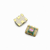
APDS-9007-020 Avago Technologies US Inc., APDS-9007-020 Datasheet - Page 11

APDS-9007-020
Manufacturer Part Number
APDS-9007-020
Description
AMBIENT LIGHT SENSOR 6CHIPLED
Manufacturer
Avago Technologies US Inc.
Type
Ambient Light Sensor with Logarithmic Current Outputr
Datasheet
1.APDS-9007-020.pdf
(14 pages)
Specifications of APDS-9007-020
Peak Wavelength
560 nm
Maximum Light Current
39 uA
Maximum Rise Time
0.2 ms
Maximum Fall Time
0.2 ms
Package / Case
Chip LED-6
Maximum Operating Temperature
+ 85 C
Mounting Style
SMD/SMT
Product
Ambient Light Sensor
Sensor Output
Current
Supply Voltage Range Dc
2V To 3.6V
Active Area
0.1540mm
External Depth
2.0mm
External Width
2.4mm
Leaded Process Compatible
Yes
Length/height, External
0.8mm
Rohs Compliant
Yes
Lead Free Status / RoHS Status
Lead free / RoHS Compliant
Lead Free Status / RoHS Status
Lead free / RoHS Compliant, Lead free / RoHS Compliant
Other names
516-1719-2
Available stocks
Company
Part Number
Manufacturer
Quantity
Price
Company:
Part Number:
APDS-9007-020
Manufacturer:
HOLTEK
Quantity:
12 000
Appendix B: Optical Window Design for APDS-9007
1.0 Optical Window Dimensions
To ensure that the performance of the APDS-9007 will
not be affected by improper window design, there are
some constraints on the dimensions and design of the
window. There is a constraint on the minimum size of
the window, which is placed in front of the photo light
sensor, so that it will not affect the angular response of
the APDS-9007. This minimum dimension that is recom-
mended will ensure at least a ±35° light reception cone.
If a smaller window is required, a light pipe or light guide
can be used. A light pipe or light guide is a cylindrical
piece of transparent plastic, which makes use of total
internal reflection to focus the light.
The thickness of the window should be kept as minimum
as possible because there is a loss of power in every
optical window of about 8% due to reflection (4% on
each side) and an additional loss of energy in the plastic
material.
Figure B1 and B2 illustrate the two types of window
that we have recommended which could either be a flat
window or a flat window with light pipe.
Figure B1. Window Size Determination for Flat Window
Figure B2. Window Design of Flat Window with Light Guide
11
Table 1 and Figure B3 below show the recommended
dimensions of the window. These dimension values are
based on a window thickness of 1.0mm with a refractive
index 1.585.
WD
Figure B3 .Recommended Window Dimensions
Table 1. Recommended minimum dimension for optical
window. All dimensions are in mm
The window should be placed directly on top of the light
receiving area (active area) of the photo sensor to achieve
better performance and if a flat window with a light pipe
is used, dimension D2 should be 1.5mm to optimize the
performance of APDS-9007.
The recommended minimum window dimension is based
on the assumption that the center of the window and the
center of the light receiving of the photo sensor are the
same. It is recommended that the tolerance for assembly
be considered as well. The recommended minimum
window size which will take into account of the assembly
tolerance is defined as:
D1 (min + assembly tolerance) = D1min + 2*(assembly
tolerance) (Dimensions are in mm)
D2 (min + assembly tolerance) = D2min + 2*(assembly
tolerance) (Dimensions are in mm)
(T+L+Z)
WD
1.5
.0
.5
3.0
Light Receving Area
WD:
D1:
T:
L:
D2:
Z:
Working Distance between
window front panel & APDS-9007
Window Diameter
Thickness
Length of Light Pipe
Light Pipe Diameter
Distance between window rear
panel and APDS-9007
D1
0.5
1.0
1.5
.0
Z
Flat Window
(L=0.0)
APDS-9007
L
Z
T
.15
.85
3.55
4.5
D1
Top View
Flat window with Light
.0/1.
D1/D2
-
-
-
Pipe
1.0/1.5/0.5
T/L/Z
-
-
-
D2 D1


