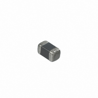
NCP15WF104J03RC Murata Electronics North America, NCP15WF104J03RC Datasheet - Page 23

NCP15WF104J03RC
Manufacturer Part Number
NCP15WF104J03RC
Description
THERMISTOR 100K OHM NTC 0402 SMD
Manufacturer
Murata Electronics North America
Series
NCP15r
Datasheet
1.NCP15WF104J03RC.pdf
(47 pages)
Specifications of NCP15WF104J03RC
Resistance In Ohms @ 25°c
100K
Resistance Tolerance
±5%
B Value Tolerance
±1%
B25/50
4250K
Operating Temperature
-40°C ~ 125°C
Power - Max
100mW
Mounting Type
Surface Mount
Package / Case
0402 (1005 Metric)
Lead Free Status / RoHS Status
Lead free / RoHS Compliant
B0/50
-
B25/75
-
B25/85
-
B25/100
-
Lead Length
-
Other names
490-2404-2
Available stocks
Company
Part Number
Manufacturer
Quantity
Price
Company:
Part Number:
NCP15WF104J03RC
Manufacturer:
MURATA
Quantity:
240 000
Part Number:
NCP15WF104J03RC
Manufacturer:
MURATA/村田
Quantity:
20 000
!Note
• This PDF catalog is downloaded from the website of Murata Manufacturing co., ltd. Therefore, it’s specifications are subject to change or our products in it may be discontinued without advance notice. Please check with our
• This PDF catalog has only typical specifications because there is no space for detailed specifications. Therefore, please approve our product specifications or transact the approval sheet for product specifications before ordering.
sales representatives or product engineers before ordering.
!Note
7. Printing Conditions of Solder Paste
8. Adhesive Application and Curing
3
NCP03
NCP15
NCP18/NCP21
The amount of solder is critical. Standard height of fillet is
shown in the table below.
Too much soldering may cause mechanical stress,
resulting in cracking, mechanical and/or electronic
damage.
Thin or insufficient adhesive may result in loose
component contact with land during flow soldering.
Low viscosity adhesive causes chips to slip after
mounting.
Continued from the preceding page.
• Please read rating and !CAUTION (for storage, operating, rating, soldering, mounting and handling) in this catalog to prevent smoking and/or burning, etc.
• This catalog has only typical specifications because there is no space for detailed specifications. Therefore, please approve our product specifications or transact the approval sheet for product specifications before ordering.
Part Number
Temp. Sensor and Compensation Chip Type !Caution/Notice
The Solder Paste Thickness
100 m
150 m
200 m
Reference: Optimum Solder Amount
E
Electrode
Solder
0.2mmVTVE
1/3EVTVE
1/3EVTVE
T
T
Solder
R44E.pdf
21
11.2.21
4


