240D10-17 OPTO 22, 240D10-17 Datasheet - Page 9
240D10-17
Manufacturer Part Number
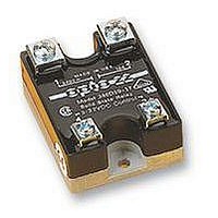
240D10-17
Description
SSR, 10A, 240VAC
Manufacturer
OPTO 22
Specifications of 240D10-17
Control Voltage Range
3Vdc To 32Vdc
Operating Voltage Range
24VAC To 280VAC
Load Current
10A
Isolation Voltage
4000V
Control Voltage Type
DC
Svhc
No SVHC (18-Jun-2010)
Approval Bodies
UL, CSA
Control Voltage
RoHS Compliant
Brand/series
DC Series
Current, Rating
10 A
Function
Timing
Mounting Type
PCB
Relay Type
Solid State
Termination
Screw
Timer Type
Off Delay
Voltage, Control
240 VAC
Relay Terminals
Screw
Rohs Compliant
Yes
Lead Free Status / Rohs Status
RoHS Compliant part


Opto 22 • 43044 Business Park Drive • Temecula, CA 92590 • Phone: (909)695-3000 • (800)321-OPTO • Fax: (909)695-3095 • Internet: www.opto22.com
Inside Sales: (800)452-OPTO • Product Support: (800)TEK-OPTO • (909)695-3080 • Fax: (909)695-3017 • E-mail: support@opto22.com • FaxBack: (800)474-OPTO
DATA SHEET
Heat Sink Calculation
Like all semiconductor devices, SSR current
ratings must be based on maximum junction
temperature. All Opto 22 SSRs operate
conservatively at maximum junction temperatures
of 110° C. Determining an adequate heat sink
for a given SSR conducting a given current is
very simple.
Note: Thermally conductive grease must be used
between the relay base and the heat sink.
Form 859-990514
Applications
Tips
Sample Calculation Given:
120-Volt, 20-Amp Load
50° C Ambient Air
Choose Model 120D25 SSR.
Calculate dissipation as: 20 amps x 1.3 Watts per amp = 26 Watts
Calculate temperature rise junction to SSR base as: 26 Watts x 1.2° C per Watt = 31.2° C
Calculate allowable temperature of heat sink by subtracting 31.2° C from 110° C allowable junction temperature:
The heat sink is in a 50°C ambient, therefore, allowable temperature rise on heat sink is: 78.8° C-50° C = 28.8° C
If heat sink is allowed to rise 28.8° C above ambient, then the thermal resistance of the heat sink is simply the 28.8° C rise divided by the 26
Watt. Any heat sink having a thermal resistance less than 1.1° C per Watt will be adequate.
Duty Cycle Calculation
When solid-state relays are operated in an on/off mode, it may be advantageous to calculate the RMS value of the current through the SSR
for heat sinking or determining the proper current rating of the SSR for the given application.
I
T
T
I
RMS
ON
1
2
= Time current is on
= Time current is off
= RMS value of load current during on period
= RMS value of load or SSR
110° C-31.2 = 78.8° C
SOLID-STATE RELAYS
I
RMS
=
(I
ON
T
1
)
+ T
2
x T
2
1
page 9/12
Related parts for 240D10-17
Image
Part Number
Description
Manufacturer
Datasheet
Request
R

Part Number:
Description:
SSR, PANEL MOUNT, 280VAC, 32VDC, 10A
Manufacturer:
OPTO 22
Datasheet:

Part Number:
Description:
240" BCM RIBBON CABLE W/ CONNECTORS
Manufacturer:
SQUARE D
Datasheet:

Part Number:
Description:
CONTACTOR; DP; 3 POLE; 40A; 240VAC COIL
Manufacturer:
Eaton / Control Automation
Datasheet:
Part Number:
Description:
CONTACTOR; DP; 3 POLE; 30A; 240VAC COIL
Manufacturer:
Eaton / Control Automation
Datasheet:
Part Number:
Description:
CONTACTOR; DP; 2 POLE; 30A; 240VAC COIL
Manufacturer:
Eaton / Control Automation
Datasheet:
Part Number:
Description:
CONTACTOR; DP; 3 POLE; 25A; 240VAC COIL
Manufacturer:
Eaton / Control Automation
Datasheet:
Part Number:
Description:
CONTACTOR; DP; 3 POLE; 50A; 240VAC COIL
Manufacturer:
Eaton / Control Automation
Datasheet:

Part Number:
Description:
Solid State Relays, Accessories
Manufacturer:
OPTO 22
Datasheet:
