D12SN6FV BANNER ENGINEERING, D12SN6FV Datasheet - Page 2
D12SN6FV
Manufacturer Part Number
D12SN6FV
Description
Photoelectric Sensor
Manufacturer
BANNER ENGINEERING
Type
High Powerr
Specifications of D12SN6FV
Sensor Output
NPN
Peak Reflow Compatible (260 C)
No
Sensor Housing
Rectangular
Sensor Input
Fiber Optic
Output Type
Transistor
Leaded Process Compatible
No
Contact Current Max
150mA
Brand/series
D12
Current, Switching
150 mA
Function
Fiber Optic
Indicator
LED
Ip Rating
IP66
Light Source
Visible
Material, Casing
Black ABS (Housing)
Material, Cover
Acrylic
Mounting Type
DIN Rail
Output
NPN
Primary Type
Photoelectric
Sensing Mode
Selectable
Standards
CE Marked
Technology
Photoelectric
Temperature, Operating
-20 to +70 °C
Termination
Cable
Time, Response
500 μs
Voltage, Supply
30 VDC
Accessories Available
Cordsets and Fiber Optic Cable
Fiber Optic Sensor Type
High Power
Lead Free Status / Rohs Status
RoHS Exempt Product
For Use With
Power on and NO output conducting


2
Specifications, D12 Series sensors
Sensing range:
Sensing beam:
Supply voltage:
Protected against reverse polarity and inductive load transients.
Output configurations:
Solid-state dc complementary outputs:
The N.C. (normally closed) output of standard FP and FV models may
be used as an alarm output, depending upon the hookup to the power
supply.
Output rating
and the other normally closed (N.C.). 150 mA maximum each output.
No false pulse on power-up. (False pulse protection circuit causes a 0.1
second delay on power-up.) Short-circuit protected.
Off-state leakage current <10 microamps at 30V dc.
On-state saturation voltage <1V at 10 mA dc; <1.5V at 150 mA dc.
The total load may not exceed 150 mA.
Response time (FV, FP models):
500 microseconds "on"; 500 microseconds "off".
Repeatability is 130 microseconds.
FVY, FVY1, FPY, and FPY1 models
500 microsecond response mode plus a high speed (50 microseconds
on/off) mode. Repeatability in the high-speed (50µs) mode is 15 mi-
croseconds. FPY1 and FVY1 models (when used in the 50µs response
mode) include a 20 ms pulse stretcher for use in applications in which
the load (or input circuit) requires a longer input signal.
Response time and repeatability are independent of signal strength.
For glass fiber optics (see page 3 for models)
D12SN6FV Series
D12SN6FVY Series
D12SN6FVY1 Series NPN sinking (high speed, with pulse stretcher)
D12SP6FV Series PNP sourcing (standard)
D12SP6FVY Series
D12SP6FVY1 Series PNP sourcing (high speed, with pulse stretcher)
For plastic fiber optics (see page 4 for models)
D12SN6FP Series
D12SN6FPY Series
D12SN6FPY1 Series NPN sinking (high speed, with pulse stretcher)
D12SP6FP Series
D12SP6FPY Series
D12SP6FPY1 Series PNP sourcing (high speed, with pulse stretcher)
Hookup Diagrams, D12 Series Sensor
Sinking (NPN)
Standard Hookup
Sourcing (PNP)
Standard Hookup
: Complementary outputs, one normally open (N.O.)
visible red, 680 nanometers.
see individual excess gain curves, pages 3 and 4.
10 to 30V dc at 45 mA max, exclusive of load.
NPN sinking (standard)
NPN sinking (high speed)
PNP sourcing (high speed)
NPN sinking (standard)
NPN sinking (high speed)
PNP sourcing (standard)
PNP sourcing (high speed)
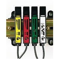
DIN Rail Fiber Optic Sensors
.
have switch-selectable standard
Sinking (NPN)
Alarm Hookup
Sourcing (PNP)
Alarm Hookup
Indicators:
green, and one seven segment red LED moving-dot bargraph. Note
that the seven segment bargraph and marginal excess gain indication
(bargraph segment #7) are inoperative in the 50µs response mode on
Y and Y1 models.
GREEN LED lights for
YELLOW LED lights for
ING
On all models in 500µs response mode, the 7-segment moving dot
red LED bargraph lights to indicate relative received light signal
strength.
#1 flashes to indicate
500µs response mode, segment #7 flashes to indicate
EXCESS GAIN
corresponds to the "on" state of the alarm output. (Alarm output not
available on Ys & Y1s.)
Adjustments:
module (15-turn slotted brass screw, clutched at both ends of adjust-
ment). FVY and FPY (high speed models) also have a top-mounted
response mode selector switch.
Construction:
cover. Rated NEMA 2; IEC IP11. The fiber clamping element is
Delrin
bracket (supplied).
Cable:
cable, or 6-inch pigtail with pico-type 4-pin QD connector.
Mounting bracket:
dard DIN rail, or may be through-hole mounted using the supplied
mounting bracket and M3 x 0,5 hardware. Bracket material is black
VALOX
Operating temperature range:
Maximum relative humidity 90% at 50°C (non-condensing).
Application caution...
D12 Series sensors are designed to deliver very high optical energy
(excess gain). They should not be used for applications which offer
low optical contrast (i.e. only a small difference in received light levels
between the light and dark sensing conditions). Examples include diffuse
mode sensing of objects in front of a reflective background and opposed
mode sensing of non-opaque materials.
D12 sensors excel in applications requiring high excess gain (e.g. for
long-range sensing, sensing with long fiber lengths, diffuse sensing of
materials with low reflectivity, etc.)
.
®
. Stainless steel M3 x 0,5 hardware for use with mounting
®
.
6-1/2-foot (2 m) or 30-foot (9 m) attached PVC-covered
On all models in 50 and 500µs response modes, segment
Two top-mounted LED indicators, one yellow and one
. On standard FV and FP models, a flashing LED
All models have a SENSITIVITY control on top of
Black ABS (Cycolac
OUTPUT OVERLOAD
D12 Series sensors mount directly to a stan-
DC POWER ON
NORMALLY OPEN OUTPUT CONDUCT-
-20° to +70°C (-5° to +158°F).
®
.
KJB) housing with acrylic
. On all models in the
MARGINAL
Related parts for D12SN6FV
Image
Part Number
Description
Manufacturer
Datasheet
Request
R

Part Number:
Description:
Photoelectric Sensor
Manufacturer:
BANNER ENGINEERING
Datasheet:

Part Number:
Description:
Photoelectric Sensor
Manufacturer:
BANNER ENGINEERING
Datasheet:

Part Number:
Description:
LEDIR70XD4-XM-81039 MAX INTENS STROBE ONLY NO BANNER MARKS
Manufacturer:
BANNER ENGINEERING
Part Number:
Description:
M18SP6DL-72225 LABELED MOELLER NO BANNER MARKINGS BULK PACK
Manufacturer:
BANNER ENGINEERING
Part Number:
Description:
M18SP6DLQ-72226 LABLED MOELLER NO BANNER MARKINGS BULK PACK
Manufacturer:
BANNER ENGINEERING
Part Number:
Description:
M18SP6L-72223 LABELED MOELLER NO BANNER MARKINGS BULK PACK
Manufacturer:
BANNER ENGINEERING
Part Number:
Description:
M18SP6LQ-72224 LABELED MOELLER NO BANNER MARKINGS BULK PACK
Manufacturer:
BANNER ENGINEERING
Part Number:
Description:
P4D1-77908 P4 DRIVER GENERIC NO BANNER MARKINGS RESALE TO CUSTOMER
Manufacturer:
BANNER ENGINEERING

Part Number:
Description:
Series D12 Expert With Automatic Sensitivity Adjustment
Manufacturer:
Banner Engineering Corp.
Datasheet:
Part Number:
Description:
Photoelectric Sensor
Manufacturer:
BANNER ENGINEERING
Datasheet:

Part Number:
Description:
Programmable Indicator Light
Manufacturer:
BANNER ENGINEERING
Datasheet:
Part Number:
Description:
INDICATOR LED PANEL 50MM GRN/RED/YEL 30V
Manufacturer:
BANNER ENGINEERING
Datasheet: