PDIS46UM12 BANNER ENGINEERING, PDIS46UM12 Datasheet - Page 2
PDIS46UM12
Manufacturer Part Number
PDIS46UM12
Description
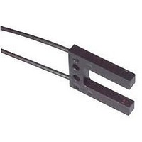
Fiber-Optic Proximity Sensor
Manufacturer
BANNER ENGINEERING
Type
Photoelectricr
Specifications of PDIS46UM12
Primary Type
Photoelectric
Fiber Optic Sensor Type
Photoelectric


Sensing Range
Implied Dimensional
Tolerance
Minimum Bend Radius
Repeat Bending/Flexing
Chemical Resistance
Temperature Extremes
Operating Temperature
Construction
1
2
3
4
5
6
P lastic fiber assemblies with “U” in the suffix of the model numbers have unterminated control ends
(the end that is coupled to the photoelectric sensor). The customer can cut these fiber optic assemblies
to the required length using the supplied cutter. Use only the supplied cutter to ensure optimal light
coupling efficiency.
T erminated plastic fiber assemblies are optically ground and polished and cannot be shortened,
spliced or otherwise modified.
D o not subject the plastic fibers to sharp bends, pinching, high tensile loads or high levels of radiation.
W hen ordering fiber lengths in excess of 2 m, take into account light signal attenuation due to the
additional length.
D ue to their light transmission properties, plastic fiber optics are recommended for use only
with visible light fiber optic sensors.
U se caution when applying fiber optics in hazardous locations. Although fiber optic assemblies are, by
themselves, intrinsically safe, the sensor and associated electronics must be LOCATED IN A SAFE
ENVIRONMENT. Alternatively, fiber optics may be used with NAMUR sensor model Q45AD9FP
(page 157). Fiber optics do not necessarily provide a hermetic seal between a hazardous environment
and the safe environment.
Optical Fiber: acrylic (PMMA) monofilament, except as noted
Protective Jacket: black polyethylene, except as noted
Threaded End Tips and Hardware: nickel-plated brass, except as noted
Probe End Tips: annealed (bendable) 304 stainless steel
Angled End tips: hardened 304 stainless steel
Ferrule End Tips: 303 stainless steel
Refer to the specific fiber optic/sensor combination
All dimensions are in millimeters: x = ±2.5 mm, x.x = ±0.25 mm and x.xx = ±0.12 mm, unless specified.
“L” = ±40 mm per meter
8 mm for 0.25 mm diameter fibers
12 mm for 0.5 mm diameter fibers (except DURA-BEND
25 mm for 1.0 mm diameter fibers (except DURA-BEND
38 mm for 1.5 mm diameter fibers
Life expectancy of plastic fiber optic cable is in excess of one million cycles at bend radii of no less than
the minimum and a bend of 90° or less. Avoid stress at the point where the cable enters the sensor
(“control end”) and at the sensing end tip. Coiled plastic fiber optic assemblies are recommended for any
application requiring reciprocating fiber motion.
The acrylic core of the monofilament optical fiber will be damaged by contact with acids, strong bases
(alkalis) and solvents. The polyethylene jacket will protect the fiber from most chemical environments.
However, materials may migrate through the jacket with long term exposure. Samples of fiber optic
material are available from Banner for testing and evaluation.
Temperatures below -30° C will cause embrittlement of the plastic materials but will not cause
transmission loss. Temperatures above +70° C will cause both transmission loss and fiber shrinkage.
-30° to +70° C, unless otherwise specified
Plastic Fiber Optics Specifications
!
A
pplicAtion
n
otes And
More information online at
W
Arnings
™
™
)
)
!
bannerengineering.com
FIBER SYSTEMS
189
Related parts for PDIS46UM12
Image
Part Number
Description
Manufacturer
Datasheet
Request
R

Part Number:
Description:
Photoelectric Sensor
Manufacturer:
BANNER ENGINEERING
Datasheet:

Part Number:
Description:
Photoelectric Sensor
Manufacturer:
BANNER ENGINEERING
Datasheet:

Part Number:
Description:
LEDIR70XD4-XM-81039 MAX INTENS STROBE ONLY NO BANNER MARKS
Manufacturer:
BANNER ENGINEERING
Part Number:
Description:
M18SP6DL-72225 LABELED MOELLER NO BANNER MARKINGS BULK PACK
Manufacturer:
BANNER ENGINEERING
Part Number:
Description:
M18SP6DLQ-72226 LABLED MOELLER NO BANNER MARKINGS BULK PACK
Manufacturer:
BANNER ENGINEERING
Part Number:
Description:
M18SP6L-72223 LABELED MOELLER NO BANNER MARKINGS BULK PACK
Manufacturer:
BANNER ENGINEERING
Part Number:
Description:
M18SP6LQ-72224 LABELED MOELLER NO BANNER MARKINGS BULK PACK
Manufacturer:
BANNER ENGINEERING
Part Number:
Description:
P4D1-77908 P4 DRIVER GENERIC NO BANNER MARKINGS RESALE TO CUSTOMER
Manufacturer:
BANNER ENGINEERING
Part Number:
Description:
Photoelectric Sensor
Manufacturer:
BANNER ENGINEERING
Datasheet:

Part Number:
Description:
Programmable Indicator Light
Manufacturer:
BANNER ENGINEERING
Datasheet:
Part Number:
Description:
INDICATOR LED PANEL 50MM GRN/RED/YEL 30V
Manufacturer:
BANNER ENGINEERING
Datasheet:
Part Number:
Description:
Programmable Indicator Light
Manufacturer:
BANNER ENGINEERING
Datasheet: