E3S-DS10E41 Omron, E3S-DS10E41 Datasheet
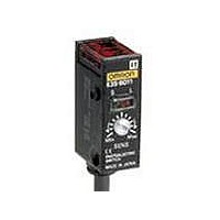
E3S-DS10E41
Specifications of E3S-DS10E41
Available stocks


Related parts for E3S-DS10E41


E3S-DS10E41 Summary of contents
Page 1
... Light-ON/Dark-ON (selectable 0 100 mm 300 100 mm (variable 250 mm (variable) CSM_E3S_DS_E_6_1 Model E3S-2E4 Emitter E3S-2LE4 Receiver E3S-2DE4 E3S-5E4 Emitter E3S-5LE4 Receiver E3S-5DE4 E3S-R2E4 E3S-DS10E4 E3S-DS30E4 E3S-2E41 Emitter E3S-2LE41 Receiver E3S-2DE41 E3S-5E41 (42) *2 Emitter E3S-5LE41 (42) Receiver E3S-5DE41 (42) E3S-R2E41 E3S-DS10E41 E3S-DS30E41 (42) *2 E3S-LS10XE4 E3S-LS20XE4 1 ...
Page 2
... The ambient operating illumination is the illumination that changes the output ±20% at 200 lx not the operational limit. Retro-re- Diffuse-reflective flective E3S- E3S-R2E4 E3S- DS10E4 E3S- E3S- DS30E41 E3S- DS30E4S R2E41 (42) DS10E41 100 mm 300 mm 0 (white paper (white paper 100 x 100 mm) Opaque: 30- Transparent, opaque mm dia ...
Page 3
... E3S-5E4 (41) (42) 240 220 200 180 160 140 120 100 80 60 Parallel movement 40 distance Y 20 Distance Distance X (m) E3S-DS30E4 (41) (42) 10 (Y) Optical axis 8 Operating position Operating 6 Standard sensing object distance (X) (100 x 100 mm 120 60 100 140 20 80 160 40 2 Operating distance 4 ...
Page 4
... Setting distance Standard sensing 10 object (black carbon Operating voltage 1 0.5 0 Set distance (mm) E3S Parallel Operating Range E3S-R2E4 (41) (42) 100 Parallel movement distance Y Distance X 0 0.4 0.8 1.2 1.6 2 2.4 2.8 3.2 Distance X (m) Load Residual Voltage Characteristics 2.0 1.5 1.0 ...
Page 5
... Black 4 mA electric Sensor main circuit Z Blue *1 Z: Zener diode ( *1: Reverse the polarity of the power supply to switch the operating mode. *2: Voltage output (when connecting transistor circuit) E3S Timing charts VDC Incident light Load 1 No incident light (relay) Light ON indicator (red) OFF ...
Page 6
... Connection ● With Relay Load Through-beam Sensors Light Interrupted and Load Operating for E3S-2E4 (41) and -5E4 (41) (42 max. Pink Receiver Emitter 12 to Blue Brown Note: The indicator will function as a light indication if the Emitter's pink wire is connected to the Receiver's black wire as indicated by the dotted line. The indicator will function as a power indicator if the Emitter's pink wire is connected to the Emitter's blue wire ...
Page 7
... Remove the distance adjustment scale once the distance has been adjusted. Put a sensing object in place, and then adjust the sensitivity. ● Adjusting the E3S-LS20XE4 Convergent-reflective Sensor Adjustment Method 1 Use this method if the sensing object is more reflective than the background ...
Page 8
... Precautions for Correct Use Do not use the product in atmospheres or environments that exceed product ratings. If the sensing object has a metallic or shiny surface, the E3S- R may not detect it properly. To avoid this situation, place the sensing object so that it is not at right angles to the Photoelectric Sensor. ...
Page 9
... Sensors with Different Orientations The E3S-5, E3S-DS30, and E3S-R2 that sense in different directions can be made. Sensing Sensing direction method E3S-5E43 Emitter Through- beam E3S-5E44 Emitter E3S-DS30E43 E3S-R2E43 Retro- reflective Diffuse- reflective Receiver Receiver E3S 9 ...
Page 10
... Note: Models numbers for Through-beam Sensors (E3S-@E4, E3S-@E41) are for sets that include both the Emitter and Receiver. The model number of the Emitter is expressed by adding "L" to the set model number (example: E3S-2LE4), the model number of the Receiver, by adding "D" (example: E3S-2DE4.) Refer to Ordering Information to confirm model numbers for Emitter and Receivers. ...
Page 11
... Lens 7.1 20 Emitter 1.6 6.5 12 Receiver 22 Two, M4 24.9 slotted hexagonal bolts (32) * The mounting bracket can also be used on side a. E3S-DS10E41 2 , Insulator diameter: 1.1 mm Sensitivity 5 11 adjuster 6 dia. 12.8 dia. 16.7 9 3.2 1.2 9 27.3 E3S-R2E41 E3S-DS30E41 2 , Insulator diameter: 1.1 mm), ...
Page 12
... The model number of the Emitter is expressed by adding "L" to the set model number (example: E3S-5LE42), the model number of the Receiver, by adding "D" (example: E3S-5DE42.) Refer to Ordering Information to confirm model numbers for Emitter and Receivers. Mounting Hole Dimensions E3S-2E4 E3S-LS10XE4 E3S-2E41 E3S-LS20XE4 E3S-DS10E4 E3S-DS10E41 2 , Receiver a* 23 20.4 10.2 (75) 1 ...
Page 13
... Applicable models: Provided with the E3S-5E4(41), E3S-DS30E4(41), E3S-R2E4(41). Note: Cannot be used for the E3S-DS10E4 (41). 92.1 82.1 Mounting Holes Two, M4 25.4 Applicable models: E3S-5E41 E3S-R2E41 E3S-DS30E41 25.4 9 29.1 60.8 Mounting Holes Two Applicable models: E3S-2E41 4 28.5 E3S-DS10E41 7.5 8 2.7 E3S 13 ...
Page 14
... Mounting Bracket will not be struck when the optical axis is adjusted. With the E3S-5E4 (41), the Spacer is not particularly required. Use the Spacer, however, to directly mount both the E3S-2E4 (41) and -5E4 (41). In the interest of product improvement, specifications are subject to change without notice. ...
Page 15
... Please read and understand this catalog before purchasing the products. Please consult your OMRON representative if you have any questions or comments. WARRANTY OMRON's exclusive warranty is that the products are free from defects in materials and workmanship for a period of one year (or other period if specified) from date of sale by OMRON. OMRON MAKES NO WARRANTY OR REPRESENTATION, EXPRESS OR IMPLIED, REGARDING NON-INFRINGEMENT, MERCHANTABILITY, OR FITNESS FOR PARTICULAR PURPOSE OF THE PRODUCTS ...