CCM02-1NO-3ROHS T30 C&K Components, CCM02-1NO-3ROHS T30 Datasheet - Page 5
CCM02-1NO-3ROHS T30
Manufacturer Part Number
CCM02-1NO-3ROHS T30
Description
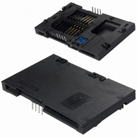
CONN SMART CARD 8PIN PCB
Manufacturer
C&K Components
Series
CCM02 MK Ir
Type
IIr
Specifications of CCM02-1NO-3ROHS T30
Card Type
Smart Card
Number Of Positions
10 (8 + 2)
Connector Type
Connector
Insertion, Removal Method
Push In, Pull Out
Mounting Type
Through Hole, Right Angle
Features
Board Guide, Switch
Height Above Board
0.228" (5.80mm)
Mounting Feature
Normal, Standard - Top
Contact Finish
Gold
Product
Card Connectors
Pitch
2.54 mm
Orientation
Right Angle
Mounting Style
SMD/SMT
Termination Style
Gullwing
Number Of Rows
2
Number Of Contacts
8
Current Rating
1 A
Contact Material
Copper Alloy
Contact Plating
Tin
Flammability Rating
UL 94 V-0
Height
5.75 mm
Insertion - Extraction Style
Hinged
Lead Free Status / RoHS Status
Lead free / RoHS Compliant
Contact Finish Thickness
-
Ejector Side
-
Other names
*CCM02-1NO-3ROHS
*CCM02-1NO-3ROHS T30
401-1904
CCM02-1NO-3 ROHS
Y1121-0207A ROHS
*CCM02-1NO-3ROHS T30
401-1904
CCM02-1NO-3 ROHS
Y1121-0207A ROHS


1 - Description
Product group : CCM02
Product Sub Family : Mk1
ROHS Compliance
Card type : Full-sized card
Contact type : Landing
Contact plating : Selective gold
Contacts number : see table p. 4
Terminal type : Thru-hole
Card end travel switch : see table
p. 4
Generic specification (C&K) :
Proc. essai 20
PRODUCT SPECIFICATION
2 – Physical data
Mass
Dimensions & lay out
3 – Using temperatures
Operating temperatures
Storage temperatures
4 - Electrical data
Voltage / ct
Current / ct
Contact resistance
Voltage proof
Insulation resistance
Card end travel switch characteristics :
Card end travel switch
sequence
5 – Mechanical data
Card insertion force
Card withdrawal force
Contact force (end travel
switch)
6 - Additional data : storage and handling environment
Marking & Traceability
Packaging conditions
Transport conditions
7 - Additional data : process environment
Soldering process
Solder heat resistance
Static load (transverse)
(CCM / PCB)
-
-
-
-
-
-
-
Max power
Max voltage
Min/Max current
Bounces
Voltage proof
Insulation resistance
Contact resistance
CCM02-MKI-ROHS
Ref./ PS-CCM02-MKI-1
6 g
According to drawing : see table page 4
- 40 °C / + 85 °C
- 40 °C / + 85 °C
Initial measurement
After damp heat
After damp heat
0.2 VA
30 Vdc
50 µA min / 10 mA max
Initial measurement
After damp heat
After damp heat
between signal contact / switch contacts &
between open contacts of the switch
Card end travel switch activates when the sliding
card is 1.0 mm from the card stop.
10 N max
1N min / 10 N max
Designation : according to drawing
Date code : year / week
30 samples per tray / 10 trays per box
Sea-air-land / World wide / High
30°C / 85% HR
According to H00-060
Single or double wave soldering process
260°C / 5 sec. According to IEC 60068-44
10N / 1 mn / 4 directions
According to IEC 512-5 test 8a/8b
0.8 N max to activate the switch
1.8 N max for complete depression
5 Vdc
10 mA
100 m
750 Vrms
0.5 ms
750Vrms
250Vrms
100 m
± 2.0
between signal contact / switch contacts
between open contacts of the switch
1 M
200 M
1 M
200 M
1000 M
1000 M
recovery time : 4 hours
recovery time : 24 hours
recovery time : 4 hours
recovery time : 24 hours
September 2008
Issue 1-rev.B
Page 5 / 6
(100 VDC)
(100 VDC)
5 m
Related parts for CCM02-1NO-3ROHS T30
Image
Part Number
Description
Manufacturer
Datasheet
Request
R


Part Number:
Description:
CONN SMART CARD 8PIN PCB
Manufacturer:
C&K Components

Part Number:
Description:
CONN SMART CARD 8PIN PCB
Manufacturer:
C&K Components

Part Number:
Description:
Rotary Switches 4P 3 POS ROTARY SW
Manufacturer:
C&K Components

Part Number:
Description:
SWITCH MODULE SPST W/CAP L130
Manufacturer:
C&K Components
Datasheet:
Part Number:
Description:
SWITCH MODULE SPST W/CAP
Manufacturer:
C&K Components
Datasheet:

Part Number:
Description:
SWITCH MODULE DPST W/CAP L130
Manufacturer:
C&K Components
Datasheet:
Part Number:
Description:
SWITCH MOD DPST W/CAP L130 PU PO
Manufacturer:
C&K Components
Datasheet:
Part Number:
Description:
SWITCH MODULE DPST W/CAP L130
Manufacturer:
C&K Components
Datasheet:
Part Number:
Description:
SWITCH MOD DPST W/CAP L130 PO PU
Manufacturer:
C&K Components
Datasheet:
Part Number:
Description:
SWITCH MOD DPST W/CAP L130 PL PR
Manufacturer:
C&K Components
Datasheet:

Part Number:
Description:
SWITCH PB SQUARE WHT MOM SPST NO
Manufacturer:
C&K Components
Datasheet:
Part Number:
Description:
SWITCH PB SQUARE GRY MOM SPST NO
Manufacturer:
C&K Components
Datasheet: