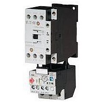
XTAE025C10A3E032 EATON CUTLER HAMMER, XTAE025C10A3E032 Datasheet - Page 278

XTAE025C10A3E032
Manufacturer Part Number
XTAE025C10A3E032
Description
Motor Starter
Manufacturer
EATON CUTLER HAMMER
Datasheet
1.XTCE007B10A.pdf
(312 pages)
Specifications of XTAE025C10A3E032
No. Of Phases
Single Or Three
Power Rating
14.5kW
Current Rating
25A
Operating Temperature Range
-25°C To +50°C
Overload Adjustment Current Min
6.4A
Power Rating, 3-phase
14.5kW
Frame Size
Standard
- Current page: 278 of 312
- Download datasheet (6Mb)
34-278
34
Auxiliary Contact Location
NEMA Sizes 00 – 2, IEC Sizes A – K
The sketches below illustrate the maximum number of auxil-
iary contacts that can be assembled to a contactor or starter
and their locations.
Table 34-351. Auxiliary Contacts
Figure 34-167. Auxiliary Contact Location
Catalog
Number
AE16
AN16
AE56
AN56
CE15
CN15
CN35
CE55
CN55
Available positions on contactors or starters other than what is factory
installed.
When a pneumatic timer is mounted on contactor, only side mounted
auxiliary contact positions are available. The solid-state timer, when
added, takes up side mounted auxiliary contact position.
Contactors and Starters
IEC Contactors & Starters
Freedom
Accessories
L1
L1
Non-reversing
Front View
Top View
Size
A – K
00
0 – 2
A – K
00 – 2
A – C
D – K
G – J
G – J
00
0 – 2
1, 2
1, 2
10A
20 – 60A
60A
60A
A – K
00 – 2
T1
T1
R1
R1
Poles
3
3
3
3
3
2 – 4
3
4
5
2 – 4
2 – 3
4
5
2 – 4
2 – 3
4
5
3
3
L1
L1
Available Mounting Positions
Open Type
T1, L1
T1, L1, R1
T1, L1
L1, R1
T1, T2
T1, L1, R1
T1, L1
T1, R1
T1
T1, L1, R1
T1, L1
T1, L1
T1, L1
T1, L1, R1
T1, L1
T1, L1
T1, L1
L1, R1
T1, T2
Contactors and Starters
T1
T1
Front View
Reversing
Top View
For more information visit: www.eaton.com
Enclosed
L1
L1
L1
L1, R1
—
L1, R1
L1
—
—
L1
L1
—
—
L1
L1
—
—
L1, R1
—
T2
T2
R1
R1
NEMA Sizes 3 – 8, IEC Sizes L – Z
The sketches below illustrate the maximum number of auxil-
iary contacts that can be assembled to a contactor and their
locations.
Note: A Base Auxiliary Contact must be added in position R1 before
additional auxiliary contacts can be mounted on NEMA Size 3 and
IEC Sizes L – N, or in L1 on NEMA Sizes 4 – 5 and IEC Sizes P – S.
Table 34-352. Auxiliary Contacts
Figure 34-168. Auxiliary Contact Location
Size
NEMA Size 3, IEC Sizes L – N
NEMA Sizes 4 – 5, IEC Sizes P – S
NEMA Sizes 6 – 7, IEC Sizes T – X
NEMA Size 8, IEC Size Z
Available positions on contactors or starters other than what is factory
installed.
Cont.
Base
Aux.
L1
of Contactor
Left Side
Cont.
Aux.
L2
Cont.
Aux.
L3
L1
L2
IEC Sizes T, U, V, W and X
NEMA Sizes 3 – 5
NEMA Sizes 6 – 7
IEC Sizes L – S
L1
NEMA Size 8
of Contactor
IEC Size Z
Front
Available Mounting Positions
R2, R3, L1, L2, L3
L2, L3, R1, R2, R3
R1
L2, R2
R1
R1
R2
Cont.
Aux.
R3
of Contactor
Right Side
Cont.
Aux.
R2
CA08102001E
March 2009
Cont.
Base
Aux.
R1
Related parts for XTAE025C10A3E032
Image
Part Number
Description
Manufacturer
Datasheet
Request
R

Part Number:
Description:
SUB FEED LUG BLOCK 150A CUTLER HAMMER TYPE BR LOADCENTER
Manufacturer:
EATON CUTLER HAMMER

Part Number:
Description:
Handle Tie Bar For (2) - 1 Pole Type BR Breakers
Manufacturer:
EATON CUTLER HAMMER

Part Number:
Description:
Type CL Breaker 25A/1Pole 120/240V 10K-Classified 1" Ckt Bkr
Manufacturer:
EATON CUTLER HAMMER


