DPM 959B LASCAR, DPM 959B Datasheet - Page 2
DPM 959B
Manufacturer Part Number
DPM 959B
Description
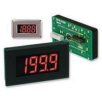
VOLTMETER, LED, 3.5DIGIT, RED
Manufacturer
LASCAR
Datasheet
1.DPM_959B.pdf
(2 pages)
Specifications of DPM 959B
Supply Voltage Range
4.75V To 5.25V
Backlighting Colour
Red
No. Of Digits / Alpha
3.5
Display Size
51mm X 24mm
Panel Cutout Height
40mm
Panel Cutout Width
72mm
Operating Temperature Range
0°C To
Lead Free Status / RoHS Status
Lead free / RoHS Compliant


PIN FUNCTIONS
SOLDER LINKS
1.
2.
3.
7.
10.
DP1-2-3.
POL.
Specifications liable to change without prior warning
10. NC
11. REF LO
12. REF HI
13. DP COM Connect to Pins 14, 15 or 16 to illuminate the required decimal point, alternatively use the on-board solder links DP1, 2 or 3.
14. DP1
15. DP2
16. DP3
1. +SEG
2. POL
3. GND
4. V+
5. V NEG
6. TEST
7. IN LO
8. IN HI
9. COM
VARIOUS OPERATING MODES
ON-BOARD SOLDER LINKS: In order to quickly and easily change operating
modes for different applications the meter has several on-board solder links.
They are designed to be easily opened (cut) or shorted (soldered). Do not connect
more than one meter to the same power supply if the meters cannot use the same
signal ground. Taking any input beyond the power supply rails will damage the
meter.
Operation with input referenced to panel
meter supply (Single ended mode).
Preferably link IN LO to GND at signal
source (to reduce loop noise), otherwise
make link 7.
Check solder links 2 & 3 are SHORTED.
Measuring current.
Supply MUST be isolated.
INPUT
VOLTAGE
Negative power supply connection (0V).
Positive power supply connection (+5V).
Output from negative rail generator (-5V nom). This is an inversion of V+.
When taken to V+ all segments, except decimal points, should light i.e. "-1888".
Negative measuring input. Analogue inputs must be no closer than 1.5V to the positive or negative supply.
Positive measuring input. The negative supply is generated internally and mirrors the positive supply voltage.
Ground for analogue section of the A/D converter, it is actively held at 3.05V below V+ and must not be allowed to sink
excessive current (>100 A) by, for instance, connecting to a higher voltage.
Do not connect.
Negative input for reference voltage. (Connected via Link 3 to COM.)
Positive input for reference voltage. (Connected via Link 1 to internal reference.)
Connect to Pin 13 to display DP1 (199.9).
Connect to Pin 13 to display DP2 (19.99).
Connect to Pin 13 to display DP3 (1.999).
Normally closed.
Normally open.
Normally closed.
Normally open.
Normally closed.
Normally open.
Normally closed.
R=
Use to indicate positive polarity- see "VARIOUS OPERATING MODES" for details.
To completely disable the negative polarity sign, cut solder link POL.
Check solder link 2 is OPEN.
I
+
0.2
FSR
-
R
7
8
8
7
IN
IN
IN HI
IN LO
LO
GND
HI
GND
V+
V+
3
4
Open this link to disable the internal reference. Then apply an external reference to REF HI (pin 12).
Close this link to connect IN LO (pin 7) to COM (pin 9).
Open this link to disconnect COM (pin 9) from REF LO (pin 11).
Close this link connect IN LO (pin 7) to GND (pin 3).
Open this link when fitting scaling resistor Ra.
Close one of these links to display decimal points DP1 (199.9), DP2 (19.99) or DP3 (1.999) respectively.
Open this link to disable the polarity sign. See Pin Functions 1 and 2 above.
4
3
0V
0V
+4.75 to +5.25V
+4.75 to +5.25V
m
LASCAR ELECTRONICS LTD.
MODULE HOUSE
WHITEPARISH
UK
TEL: +44 (1794) 884567
FAX: +44 (1794) 884616
E-mail: sales@lascar.co.uk
Measuring the ratio of two voltages.
Reading = 1000 V /V
50mV< V <200mV
V <2V .
Measuring 4-20mA to read 0-999
(supply MUST be isolated).
1
Check solder links 1 & 3 are OPEN.
+4.75 to +5.25V
V
V
DPM 959B
2
6R2
1
2
WILTSHIRE
Check solder link 2 is OPEN.
I
OUT
+
+
I
-
2
-
IN
220k
5k
Set
Zero
12
11
8
9
7
SP5 2SJ
8
7
1
IN HI
COM
IN LO
IN LO
REF LO
IN HI
REF HI
2
GND
GND
Issue 8
V+
V+
4
3
3
4
0V
0V
+4.75 to +5.25V
+4.75 to +5.25V
October/2003
(Pin 4)
0V
(Pin 3)
POL
(Pin 2)
LASCAR ELECTRONICS INC.
3750 WEST 26th STREET
ERIE
USA
TEL: +1 (814) 835 0621
FAX: +1 (814) 838 8141
E-mail: us-sales@lascarelectronics.com
The above circuit can be used to
indicate both positive and negative
polarity, by illuminating either the
+ or - segment on the meter.
Input
Voltage
Operation with input floating
with respect to power supply.
Normally
SHORTED
Cut to
OPEN
10K
PA 16506
Check solder link 2 is SHORTED.
+4.75 to +5.25V
M.C.
+
1K0
-
BC307
Applies to DPM 959B/1
7
8
IN HI
IN LO
10K
GND
V+
3
4
1K5
0V
Normally
OPEN
Solder to
SHORT
BC307
(Pin 1)
+SEG
Related parts for DPM 959B
Image
Part Number
Description
Manufacturer
Datasheet
Request
R

Part Number:
Description:
Voltmeter, Digital; Voltmeter Meter Type; LCD; 0.75 in.; 9 VDC (Typ.)
Manufacturer:
Lascar Electronics
Datasheet:

Part Number:
Description:
DPM, LED, 3.5DIGIT
Manufacturer:
LASCAR
Datasheet:

Part Number:
Description:
DPM, LCD, 3.5DIGIT, MINI
Manufacturer:
LASCAR
Datasheet:

Part Number:
Description:
DPM, LCD, 4.5DIGIT, MINI
Manufacturer:
LASCAR
Datasheet:

Part Number:
Description:
DPM, LCD, 3.5DIGIT
Manufacturer:
LASCAR
Datasheet:
Part Number:
Description:
DPM, LCD, 3.5DIGIT, NEGATIVE RAIL
Manufacturer:
LASCAR
Datasheet:

Part Number:
Description:
DPM, LCD, 3.5DIGIT
Manufacturer:
LASCAR
Datasheet:
Part Number:
Description:
DPM, LCD, 3.5DIGIT
Manufacturer:
LASCAR
Datasheet:
Part Number:
Description:
DPM, LCD, 3.5DIGIT, NEGATIVE RAIL
Manufacturer:
LASCAR
Datasheet:

Part Number:
Description:
Voltage Meter
Manufacturer:
LASCAR
Datasheet:

Part Number:
Description:
VOLTMETER, LCD, 3.5DIGIT, 35MM
Manufacturer:
LASCAR
Datasheet:

Part Number:
Description:
VOLTMETER, LCD, 3.5DIGIT, 40MM
Manufacturer:
LASCAR
Datasheet:

Part Number:
Description:
Voltage Meter
Manufacturer:
LASCAR
Datasheet:

Part Number:
Description:
Status Indicator
Manufacturer:
LASCAR
Datasheet:
Part Number:
Description:
Power Supply, Benchtop, 1.5 - 30Vdc (0-1 Amp)
Manufacturer:
Lascar Electronics
Datasheet: