SNAP-ODC-32-SNK-FM OPTO 22, SNAP-ODC-32-SNK-FM Datasheet - Page 4
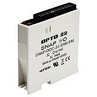
SNAP-ODC-32-SNK-FM
Manufacturer Part Number
SNAP-ODC-32-SNK-FM
Description
SNAP 32-channel High-Density Digital Output Module, 5-60 VDC Load Sinking-FM Approved
Manufacturer
OPTO 22
Datasheet
1.SNAP-HD-BF6.pdf
(17 pages)
Specifications of SNAP-ODC-32-SNK-FM
Voltage Rating
24VDC
Current Rating
150mA
Length
82.8mm
External Width
82.55mm
External Depth
18.29mm
Accessory Type
Digital Output Module


PAGE
4
Comparing SNAP High-Density and 4-Channel Digital Modules
Opto 22 • 43044 Business Park Drive • Temecula, CA 92590-3614 • www.opto22.com
SALES 800-321-6786 • 951-695-3000 • FAX 951-695-3095 • sales@opto22.com • SUPPORT 800-835-6786 • 951-695-3080 • FAX 951-695-3017 • support@opto22.com
© 2006–2011 Opto 22. All rights reserved. Dimensions and specifications are subject to change. Brand or product names used herein are trademarks or registered trademarks of their respective companies or organizations.
Number of points
on module
Isolation and fusing
Status LEDs
Polling time from I/
O processor to
module
Module turn-on/off
time
On/off status
Input latching
Counting on digital
input modules
Watchdog timer
Pulse generation
On-pulse, off-pulse,
and Period mea-
surement
Frequency
Totalizer
Digital events
1 Actual turn-on and turn-off times equal the polling time plus the module time.
2 Polling time varies based on the SNAP I/O processor (brain or on-the-rack controller), processor configuration, and Ethernet
host communication activity.
3 The high-density digital module uses a 16-bit counter, but the processor used with the module accumulates counts to 32 bits
by periodically getting and clearing the module’s counts and adding to current values. Update time varies based on number of
modules and Ethernet communication demands.
4 Including -FM (Factory Mutual approved) and -W (Wired+Wireless) models.
1
1
Item
16-point input modules: Each point is optically iso-
lated from other points on the module.
32-point input and output modules: The module is
divided into four groups of eight points. Groups are
isolated from each other, but points within a group
are not isolated from each other. Groups must be
externally fused.
None; use the handheld OptoTerminal-G20 for mod-
ule diagnostics and commissioning, or for 32-point
modules, connect to an optional breakout rack.
2–30 ms typical
16-point input modules: 15–20 ms
32-point input modules: 6 ms
Output modules: 100 microseconds
Counting occurs on the module.
Counting is available with SNAP-PAC-R1
PAC-EB1
Counting speeds:
On 32-point modules, 0–50 Hz @ 50% duty cycle
On 16-point modules, 0–25 Hz @ 50% duty cycle
(Speed depends on module; see specifications for
each part number.)
Firmware 8.1 and higher, yes.
Firmware 8.0 and lower, no.
Firmware 8.1 and higher, yes.
Firmware 8.0 and lower, no.
SNAP High-Density Digital Modules
4
, and SNAP-PAC-SB1 processors.
16 or 32, depending on module
2
SNAP High-Density Digital I/O Modules
Yes
Yes
Yes
No
No
No
3
4
, SNAP-
Input modules: Each point is optically isolated
from other points on the module.
Most output modules: Points are not isolated
from each other. Points share a common fuse. For
isolated modules, see the SNAP Digital Ouput
Modules Data Sheet (form #1144).
One for each point, located on top of module.
0.5–2 ms typical
Varies by module. Examples:
•
•
High-speed counting occurs on the I/O processor
(brain or on-the-rack controller) and can be config-
ured for any point. (High-speed counting is avail-
able on SNAP-PAC-R1
SNAP-PAC-SB1 processors.)
Counting speed varies based on the processor
and the speed of the module. Example: SNAP-
PAC-EB1 brain with SNAP-IDC5-FAST: up to 20
KHz
SNAP-IDC5-FAST: 25 microseconds
SNAP-IDC5: 5 ms turn-on, 15 ms turn-off
4-Channel SNAP Digital Modules
2
4
Yes
Yes
Yes
Yes
Yes
Yes
Yes
Yes
, SNAP-PAC-EB1
4
4
, and
Related parts for SNAP-ODC-32-SNK-FM
Image
Part Number
Description
Manufacturer
Datasheet
Request
R

Part Number:
Description:
I/O Module
Manufacturer:
OPTO 22
Datasheet:
Part Number:
Description:
I/O Module
Manufacturer:
OPTO 22
Datasheet:

Part Number:
Description:
SNAP 32-channel High-Density Digital Output Module, 5-60 VDC Load Sourcing-FM Approved
Manufacturer:
OPTO 22
Part Number:
Description:
Fused Breakout Rack For SNAP High-density Digital Output Modules-FM Approved
Manufacturer:
OPTO 22

Part Number:
Description:
DOUBLE ROW MINI LATCH HOUSING
Manufacturer:
OPTO 22
Datasheet:
Part Number:
Description:
SSR, PANEL MOUNT, 280VAC, 32VDC, 10A
Manufacturer:
OPTO 22
Datasheet:

Part Number:
Description:
SSR, PANEL MOUNT, 280VAC, 32VDC, 25A
Manufacturer:
OPTO 22
Datasheet:
Part Number:
Description:
SSR, PANEL MOUNT, 280VAC, 32VDC, 25A
Manufacturer:
OPTO 22
Datasheet:
Part Number:
Description:
SSR, PANEL MOUNT, 280VAC, 32VDC, 45A
Manufacturer:
OPTO 22
Datasheet:
Part Number:
Description:
SSR, PANEL MOUNT, 280VAC, 32VDC, 45A
Manufacturer:
OPTO 22
Datasheet:

Part Number:
Description:
Solid State Relays, Accessories
Manufacturer:
OPTO 22
Datasheet:
