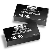
UEP-3.3/4500-D12-C Murata Power Solutions Inc, UEP-3.3/4500-D12-C Datasheet - Page 6

UEP-3.3/4500-D12-C
Manufacturer Part Number
UEP-3.3/4500-D12-C
Description
DC/DC TH 4.5A 12-3.3V UEP
Manufacturer
Murata Power Solutions Inc
Series
UEPr
Specifications of UEP-3.3/4500-D12-C
Product
Isolated
Output Power
15 W
Input Voltage Range
10 V to 18 V
Number Of Outputs
1
Output Voltage (channel 1)
3.3 V
Output Current (channel 1)
4.5 A
Isolation Voltage
1.5 KV
No. Of Outputs
1
Input Voltage
10V To 18V
Power Rating
14.85W
Output Voltage
3.3V
Output Current
4.5A
Approval Bodies
EN / UL
Supply Voltage
12V
Dc / Dc Converter Case Style
Through Hole
Rohs Compliant
Yes
Lead Free Status / Rohs Status
Lead free / RoHS Compliant
Short Circuit Condition
When a converter is in current limit mode the output voltages will drop as the
output current demand increases. If the output voltage drops too low, the
magnetically coupled primary side voltages will also drop, thereby shutting
down the PWM controller.
Following a time-out period, the PWM will restart, causing the output voltage to
begin ramping to its appropriate value. If the short-circuit condition persists,
another shutdown cycle will be initiated. This on/off cycling is referred to
as "hiccup" mode. The hiccup cycling reduces the average output current,
thereby preventing internal temperatures from rising to excessive levels. The
UEP is capable of enduring an indefinite short circuit output condition.
Thermal Shutdown
These UEP converters are equipped with Thermal Shutdown Circuitry. If envi-
ronmental conditions cause the internal temperature of the DC/DC converter
rises above the designed operating temperature (typically 118°C case), a
precision temperature sensor will power down the unit. When the internal
temperature decreases below the threshold of the temperature sensor the unit
will self start.
Output Overvoltage Protection
Output voltages are monitored for an overvoltage condition via magnetic
coupling to the primary side. If the output voltage should rise to a level which
could be damaging to the load circuitry, the sensing circuitry will power down
the PWM controller causing the output voltages to decrease. Following a
time-out period the PWM will restart, causing the output voltages to ramp to
their appropriate values. If the fault condition persists, and the output voltage
again climbs to excessive levels, the overvoltage circuitry will initiate another
shutdown cycle. This on/off cycling is referred to as “hiccup” mode.
Soldering Guidelines
Murata Power Solutions recommends the specifications below when installing these
converters. These specifications vary depending on the solder type. Exceeding these
specifications may cause damage to the product. Be cautious when there is high atmo-
spheric humidity. We strongly recommend a mild pre-bake (100° C. for 30 minutes). Your
production environment may differ; therefore please thoroughly review these guidelines
with your process engineers.
For Sn/Ag/Cu based solders:
Maximum Preheat Temperature
Maximum Pot Temperature
Maximum Solder Dwell Time
For Sn/Pb based solders:
Maximum Preheat Temperature
Maximum Pot Temperature
Maximum Solder Dwell Time
Wave Solder Operations for through-hole mounted products
(THMT)
115° C.
270° C.
7 seconds
105° C.
250° C.
6 seconds
www.murata-ps.com
Ultra-High Density, 2" x 1", 1.2-6 Amp,15-30 Watt DC/DC’s
17.5
12.5
7.5
2.5
15
10
5
0
–40
Single Output UEP Models
Temperature Derating Curves for UEP-3.3/4500 Output Models
0
40
Technical enquiries email: sales@murata-ps.com, tel:
45
50
V
V
IN
IN
Ambient Temperature (
55
= 18V-30V (D24)
= 36V-60V (D48)
60
V
V
V
IN
IN
IN
= 12V (D12)
= 18V-36V (D24)
= 36V-75V (D48)
65
70
MDC_UEP Models.B02 Page 6 of 11
75
°
C)
V
V
80
IN
IN
= 18V-27V (D24)
= 36V-48V (D48)
85
+1 508 339 3000
90
95
100


