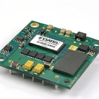
UCH-12/12.5-D48PB-C Murata Power Solutions Inc, UCH-12/12.5-D48PB-C Datasheet - Page 3

UCH-12/12.5-D48PB-C
Manufacturer Part Number
UCH-12/12.5-D48PB-C
Description
DC/DC
Manufacturer
Murata Power Solutions Inc
Datasheet
1.UCH-3.310-D48NB-C.pdf
(18 pages)
Specifications of UCH-12/12.5-D48PB-C
Product
Isolated
Output Power
150 W
Input Voltage Range
36 V to 75 V
Output Voltage (channel 1)
12 V
Output Current (channel 1)
12.5 A
Isolation Voltage
2.25 KV
Lead Free Status / Rohs Status
Lead free / RoHS Compliant
(10.2)
0.40
0.18
(4.6)
A
0.015 min. clearance
between standoffs and
highest component
Bottom View
Pin 2 may be removed under special order.
The case pin 2 is normally only used in
combination with the baseplate. Please
contact Murata Power Solutions.
(48.26)
(58.4)
1.900
Standard pin length is shown. Please refer to the Part Number Structure
for special order pin lengths.
2.30
1
2
3
4
5
6
7
8
9
On/Off Control
+Output
−Output
+Sense
−Sense
−Input
+Input
Case
Trim
A
(10.16)
0.400
www.murata-ps.com
0.20
(5.1)
Pin Diameters:
Pins 1-4, 6-8
Pins 5, 9
(12.70)
(17.78)
0.700
0.50
User’s thermal surface and hardware
Recommended threaded insert torque
is 0.35-0.55 N-M or 3-5 in-lbs.
(25.40)
1.000
Dimensions are in inches (mm) shown for ref. only.
0.040 ± 0.001 (1.016 ±0.025)
0.080 ± 0.001 (2.032 ±0.025)
B
(35.56)
1.400
Components are shown for reference only.
Tolerances (unless otherwise specified):
.XX ± 0.02 (0.5)
.XXX ± 0.010 (0.25)
Angles ± 2˚
(60.96)
2.40
B
(12.7)
0.50
1.8−15V Output DC/DC Converters
M3 x 0.50
threaded insert
and standoff (4 places)
UCH with Optional Baseplate
Screw length must
not go through Baseplate
0.18
(4.6)
2.30 (58.4)
1.90 (48.3)
Baseplate
Isolated, “Half-Brick”
(50.8)
2.00
0.015 minimum
clearance between
standoffs and
highest component
Do not remove
M3 x 0.50
threaded inserts
from bottom PCB
Page 3 of 18
(61.0)
2.40


