3120-F311-W01X-10A ETA, 3120-F311-W01X-10A Datasheet - Page 10
3120-F311-W01X-10A
Manufacturer Part Number
3120-F311-W01X-10A
Description
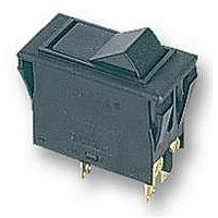
CIRCUIT BREAKER, 10A, 1POLE
Manufacturer
ETA
Datasheet
1.3120-F311-W01X-10A.pdf
(16 pages)
Specifications of 3120-F311-W01X-10A
Voltage Rating Vdc
50V
Voltage Rating Vac
250V
Fuse Current
10A
No. Of Poles
1
Mounting Type
Panel
Approval Bodies
CSA, SEMKO, UL, VDE
Breaking Capacity Current Ac
200A
Current Rating
10A
External
RoHS Compliant
Svhc
No SVHC (15-Dec-2010)
Rohs Compliant
Yes


1
Type No.
3120
3120 - F 3 2 F - N7 T1 - S GRX L 4 - 10 A
3120 - F 3 0 F - N7 Q1 - S
N.B.
Switch only versions must be specified with -N7 or -G7 terminals.
Terminals 12(k) and 22 (k) are not fitted.
Ordering information
push button switch/circuit breaker
Mounting
F
snap in frame
Size of frame
2
3
flange mounting, special frame for fitting splash cover
to fit mounting cut-out 50.5 x 21.5 mm (1.99 x 8.47 in)
panel thickness 1 - 6.35 mm (.039 - .250 in)
Number of poles
0
1
2
5
6
2 pole, unprotected, switch only
1 pole, thermally protected
2 pole, thermally protected
2 pole, thermally protected on one pole only (terminals 11,12k,12i)
1 pole, unprotected, switch only
Mounting frame design
F
G
with 2 push buttons
with 1 push button (switch-on only)
Terminal configuration
P7
H7
N7
G7
blade terminals 2x2.8x0.8mm(QC 2x.110)
(terminals 12(k), 22(k), 11, 21), not for under voltage
module, not for switch
12(k), 22(k): blade terminals 2x2.8-0.8 (QC 2x.110)
11, 21: terminal screws, not for switch
as P7, but including shunt terminals 12(i) and 22 (i)
as blade terminals 2x2.8x0.8 mm (QC 2x.110)
not for under voltage module
as H7, but including shunt terminals 12(i) and 22 (i)
as blade terminals 2x2.8x0.8 mm (QC 2x.110)
Characteristic curve
T1
Q1
Thermal Overcurrent Circuit Breaker 3120-F...
thermal, 1.01-1.4 I
switch only, only for N7 or G7 terminals
Switch style/colour
D
Z
S
1 push button (re-set only)
1 push button (momentary switch)
01X
04X
12X
19X
2 push buttons on/off
GRX
WRX
WBX
...
black
red
white translucent
green translucent
green translucent/red
white translucent/red
white translucent/black
Push button illumination (optional)
B
L
G
Y
R
. . - 20 A
filament AC/DC
neon, AC
green LED, AC/DC
yellow LED, AC/DC
red LED, AC/DC
Illumination voltage range (optional)
0
1
2
3
4
5
4 - 7 V (B,G,Y,R)
10 - 14 V (B,G,Y,R)
20 - 28 V (B,G,Y,R)
90 - 140 V (L)
185 - 275 V (L)
42 - 54 V (B,Y,R)
Current ratings
0.1...20 A
N
ordering example
switch only
www.e-t-a.com
single or double pole load
0.1 … 2 A
2.5 … 20 A
Typical time/current characteristics
The time/current characteristic curve depends on the ambient temperature
prevailing. In order to eliminate nuisance tripping, please multiply the circuit
breaker current ratings by the derating factor shown below. See also
section 9 – Technical information.
Ambient temperature °F
Derating factor
10000
10000
1000
1000
100
100
0.1
0.1
10
10
1
1
1
1
°C
2
2
… times rated current
… times rated current
-22 -4
-30 -20
0.8 0.76 0.84 0.92 1
4
4
6
6
8 10
8 10
+14 +32 +73.4 +104 +122 +140
-10
0
20
20
+23
40
40
+40 +50
1.08 1.16 1.24
05/06
+73.4 °F
+73.4 °F
+140 °F
+140 °F
+23 °C
+23 °C
+60 °C
+60 °C
-30 °C
-30 °C
-22 °F
-22 °F
(280405)
+60
Related parts for 3120-F311-W01X-10A
Image
Part Number
Description
Manufacturer
Datasheet
Request
R

Part Number:
Description:
CIRCUIT BREAKER, 16A, 1POLE
Manufacturer:
ETA
Datasheet:

Part Number:
Description:
WALL TERMINATION ANGLE / BLIND END
Manufacturer:
THOMAS & BETTS

Part Number:
Description:
VIDEO CLARIFIER EVD1000 128-TQFP
Manufacturer:
Enhanced Video Devices Inc

Part Number:
Description:
VIDEO CLARIFIER EVD1500 128-TQFP
Manufacturer:
Enhanced Video Devices Inc

Part Number:
Description:
Ac-dc Converter Power Supply
Manufacturer:
ETA-USA
Datasheet:
Part Number:
Description:
Ac/dc Switching Power Supply
Manufacturer:
ETA-USA
Datasheet:
Part Number:
Description:
Ac/dc Switching Power Supply
Manufacturer:
ETA-USA
Datasheet: