NTE5415 NTE ELECTRONICS, NTE5415 Datasheet
NTE5415
Manufacturer Part Number
NTE5415
Description
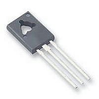
SCR THYRISTOR, 2.6A, 400V, TO-126
Manufacturer
NTE ELECTRONICS
Datasheet
1.NTE5415.pdf
(3 pages)
Specifications of NTE5415
Peak Repetitive Off-state Voltage, Vdrm
400V
Gate Trigger Current Max, Igt
0.2mA
Current It Av
2.6A
Peak Non Rep Surge Current Itsm 50hz
35A
Holding Current Max Ih
10mA
Lead Free Status / RoHS Status
Lead free / RoHS Compliant


Description:
The NTE5411 through NTE5416 are PNPN silicon controlled rectifier (SCR) devices designed for
high volume consumer applications such as temperature, light, and speed control: process and re-
mote control, and warning systems where reliability of operation is important.
Features:
D Passivated Surface for Reliability and Uniformity
D Power Rated at Economical Prices
D Practical Level Triggering and Holding Characteristics
Absolute Maximum Ratings: (T
Repetitive Peak Forward and Reverse Blocking Voltage, V
(1/2 Sine Wave, R
Non−Repetitive Peak Reverse Blocking Voltage , V
(1/2 Sine Wave, R
Average On−State Current, I
Surge On−State Current (T
Circuit Fusing (t = 8.3ms), I
Peak Gate Power (Pulse Width = 10μs, T
Note 1. Ratings apply for zero or negative gate voltage. Devices shall not have a positive bias ap-
NTE5411
NTE5412
NTE5413
NTE5414
NTE5415
NTE5416
NTE5411
NTE5412
NTE5413
NTE5414
NTE5415
NTE5416
T
T
1/2 Sine wave, 60Hz
1/2 Sine wave, 1.5ms
C
C
plied to the gate concurrently with a negative potential on the anode. Devices should not
be tested with a constant current source for forward or reverse blocking capability such that
the voltage applied exceeds the rated blocking voltage.
= −40° to +110°C
= +100°C
. . . . . . . . . . . . . . . . . . . . . . . . . . . . . . . . . . . . . . . . . . . . . . . . . . . . . . . . . . . . . . . . . . . .
. . . . . . . . . . . . . . . . . . . . . . . . . . . . . . . . . . . . . . . . . . . . . . . . . . . . . . . . . . . . . . . . . . . .
. . . . . . . . . . . . . . . . . . . . . . . . . . . . . . . . . . . . . . . . . . . . . . . . . . . . . . . . . . . . . . . . . . .
. . . . . . . . . . . . . . . . . . . . . . . . . . . . . . . . . . . . . . . . . . . . . . . . . . . . . . . . . . . . . . . . . . .
. . . . . . . . . . . . . . . . . . . . . . . . . . . . . . . . . . . . . . . . . . . . . . . . . . . . . . . . . . . . . . . . . . .
. . . . . . . . . . . . . . . . . . . . . . . . . . . . . . . . . . . . . . . . . . . . . . . . . . . . . . . . . . . . . . . . . . .
. . . . . . . . . . . . . . . . . . . . . . . . . . . . . . . . . . . . . . . . . . . . . . . . . . . . . . . . . . . . . . . . . . .
. . . . . . . . . . . . . . . . . . . . . . . . . . . . . . . . . . . . . . . . . . . . . . . . . . . . . . . . . . . . . . . . . . .
. . . . . . . . . . . . . . . . . . . . . . . . . . . . . . . . . . . . . . . . . . . . . . . . . . . . . . . . . . . . . . . . . . .
. . . . . . . . . . . . . . . . . . . . . . . . . . . . . . . . . . . . . . . . . . . . . . . . . . . . . . . . . . . . . . . . . . .
. . . . . . . . . . . . . . . . . . . . . . . . . . . . . . . . . . . . . . . . . . . . . . . . . . . . . . . . . . . . . . . . . . .
. . . . . . . . . . . . . . . . . . . . . . . . . . . . . . . . . . . . . . . . . . . . . . . . . . . . . . . . . . . . . . . . . . .
GK
GK
. . . . . . . . . . . . . . . . . . . . . . . . . . . . . . . . . . . . . . . . . . . . . . . . . . . . . . . . . . . . . . . .
= 1000Ω, T
= 1000Ω, T
Silicon Controlled Rectifier (SCR)
C
2
4 Amp, Sensitive Gate, TO126
t
. . . . . . . . . . . . . . . . . . . . . . . . . . . . . . . . . . . . . . . . . . . . . . . . . . . . . . . . .
. . . . . . . . . . . . . . . . . . . . . . . . . . . . . . . . . . . . . . . . . . . . . . . . . . . . . . . . . .
T(AV)
= +90°C), I
. . . . . . . . . . . . . . . . . . . . . . . . . . . . . . . . . . . . . . . . . . . . . . . . . . . . . . . . .
. . . . . . . . . . . . . . . . . . . . . . . . . . . . . . . . . . . . . . . . . . . . . . . . . . . . .
NTE5411 thru NTE5416
C
C
C
= −40° to +110°C, Note 1)
= −40° to +110°C)
= +110°C unles otherwise specified)
TSM
C
= +90°C), P
RSM
GM
DRM
. . . . . . . . . . . . . . . . . . . . . . . . . . . . . .
, V
RRM
2.6A
100V
200V
400V
600V
100V
100V
150V
250V
450V
650V
0.5W
2.6A
1.6A
30V
60V
25A
35A
2
s
Related parts for NTE5415
Image
Part Number
Description
Manufacturer
Datasheet
Request
R

Part Number:
Description:
Replacement Semiconductors TO-220 NPN HI-FQ DRV
Manufacturer:
NTE ELECTRONICS
Datasheet:

Part Number:
Description:
ICS,NTE LED FLASHLIGHTS,ICS,RED TRAFFIC AND SAFETY WAND FOR LW-PRO4000-BLK. MOLDED TRANSLUCENT PLASTIC WAND,TASK LIGHTING,LIGHTWAVE? LED FLASHLIGHTS ,NTE ELECTRONICS
Manufacturer:
NTE ELECTRONICS

Part Number:
Description:
Fuse; Non-Resettable; 15A; Dims 0.16x0.457"; Axial; 120-277VAC; PCB; NTE Series
Manufacturer:
NTE Electronics, Inc.
Datasheet:
Part Number:
Description:
Fuse; Non-Resettable; 15A; Dims 0.16x0.457"; Axial; 120-277VAC; PCB; NTE Series
Manufacturer:
NTE Electronics, Inc.
Datasheet:
Part Number:
Description:
Fuse; Non-Resettable; 15A; Dims 0.16x0.457"; Axial; 120-277VAC; PCB; NTE Series
Manufacturer:
NTE Electronics, Inc.
Datasheet:
Part Number:
Description:
Fuse; Non-Resettable; 15A; Dims 0.16x0.457"; Axial; 120-277VAC; PCB; NTE Series
Manufacturer:
NTE Electronics, Inc.
Datasheet:
Part Number:
Description:
Fuse; Non-Resettable; 15A; Dims 0.16x0.457"; Axial; 120-277VAC; PCB; NTE Series
Manufacturer:
NTE Electronics, Inc.
Datasheet:
Part Number:
Description:
Fuse; Non-Resettable; 15A; Dims 0.16x0.457"; Axial; 120-277VAC; PCB; NTE Series
Manufacturer:
NTE Electronics, Inc.
Datasheet:
Part Number:
Description:
Fuse; Non-Resettable; 15A; Dims 0.16x0.457"; Axial; 120-277VAC; PCB; NTE Series
Manufacturer:
NTE Electronics, Inc.
Datasheet:
Part Number:
Description:
Fuse; Non-Resettable; 15A; Dims 0.16x0.457"; Axial; 120/250VAC; PCB; NTE Series
Manufacturer:
NTE Electronics, Inc.
Datasheet:
Part Number:
Description:
MOTOR START AC ELECTROLYTIC
Manufacturer:
NTE [NTE Electronics]
Datasheet:
Part Number:
Description:
SOLID TANTALUM
Manufacturer:
NTE [NTE Electronics]
Datasheet:
Part Number:
Description:
HIGH-FREQ ALUMINUM ELECTROLYTIC
Manufacturer:
NTE [NTE Electronics]
Datasheet:
Part Number:
Description:
SNAP-IN MOUNT ALUMINUM ELECTROLYTIC
Manufacturer:
NTE [NTE Electronics]
Datasheet:

Part Number:
Description:
Replacement Semiconductors TO-220 NPN PWR AMP
Manufacturer:
NTE ELECTRONICS
Datasheet:
NTE5415 Summary of contents
Page 1
... NTE5415 . . . . . . . . . . . . . . . . . . . . . . . . . . . . . . . . . . . . . . . . . . . . . . . . . . . . . . . . . . . . . . . . . . . ...
Page 2
Average Gate Power (t = 8.2ms, T Peak Forward Gate Current, I Peak Reverse Gate Voltage, V Operating Junction Temperature Range, T Storage Temperature Range, T Thermal Resistance, Junction−to−Case, R Thermal Resistance, Junction−to−Ambient, R Mounting Torque (Note 2) Note 2. ...
Page 3
Max .450 (11.4) Max .655 (16.6) Max K A .130 (3.3) Max .175 (4.45) Max .118 (3.0) Dia .030 (.762) Dia G .090 (2.28) ...