NTE5427 NTE ELECTRONICS, NTE5427 Datasheet
NTE5427
Manufacturer Part Number
NTE5427
Description
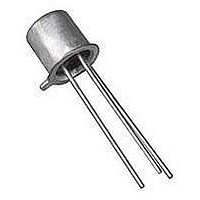
SCR THYRISTOR, 7A, 200V, TO-5
Manufacturer
NTE ELECTRONICS
Datasheet
1.NTE5427.pdf
(2 pages)
Specifications of NTE5427
Peak Repetitive Off-state Voltage, Vdrm
200V
Gate Trigger Current Max, Igt
25mA
On State Rms Current It(rms)
7A
Peak Non Rep Surge Current Itsm 50hz
80A
Holding Current Max Ih
50mA
Lead Free Status / RoHS Status
Lead free / RoHS Compliant


Absolute Maximum Ratings:
Repetitive Peak Reverse Voltage (T
Repetitive Peak Off−State Voltage (T
RMS On−State Current (T
Peak Surge (Non−Repetitive) On−State Current (One Cycle at 50 or 60Hz), I
Peak Gate−Trigger Current (3μs Max), I
Peak Gate−Power Dissipation (I
Average Gate Power Dissipation, P
Operating Temperature Range, T
Storage Temperature Range, T
Typical Thermal Resistance, Junction−to−Case, R
Electrical Characteristics: (T
Peak Off−State Current
Maximum On−State Voltage
DC Holding Current
DC Gate−Trigger Current
DC Gate−Trigger Voltage
Gate Controlled Turn−On Time
I
Critical Rate of Off−State Voltage
2
t for Fusing Reference
NTE5427
NTE5428
NTE5429
NTE5427
NTE5428
NTE5429
Parameter
. . . . . . . . . . . . . . . . . . . . . . . . . . . . . . . . . . . . . . . . . . . . . . . . . . . . . . . . . . . . . . . . . . .
. . . . . . . . . . . . . . . . . . . . . . . . . . . . . . . . . . . . . . . . . . . . . . . . . . . . . . . . . . . . . . . . . . .
. . . . . . . . . . . . . . . . . . . . . . . . . . . . . . . . . . . . . . . . . . . . . . . . . . . . . . . . . . . . . . . . . . .
. . . . . . . . . . . . . . . . . . . . . . . . . . . . . . . . . . . . . . . . . . . . . . . . . . . . . . . . . . . . . . . . . . .
. . . . . . . . . . . . . . . . . . . . . . . . . . . . . . . . . . . . . . . . . . . . . . . . . . . . . . . . . . . . . . . . . . .
. . . . . . . . . . . . . . . . . . . . . . . . . . . . . . . . . . . . . . . . . . . . . . . . . . . . . . . . . . . . . . . . . . .
Silicon Controlled Rectifier (SCR)
C
= +80°C, Conduction Angle of 180°), I
stg
C
GT
NTE5427 thru NTE5429
Symbol
opr
= +25°C unless otherwise specified)
(critical)
I
dv/dt
I
I
HOLD
V
V
RRM
DRM
. . . . . . . . . . . . . . . . . . . . . . . . . . . . . . . . . . . . . . . . . .
I
≤ I
G(AV)
I
t
GT
C
TM
GT
gt
2
C
t
. . . . . . . . . . . . . . . . . . . . . . . . . . . . . . . . . . . . . . . .
GTM
= +110°C), V
= +110°C), V
GTM
7 Amp, TO5
), P
V
T
I
V
V
I
For SCR Protection
Gate Open, T
. . . . . . . . . . . . . . . . . . . . . . . . . . . . . . . . . . . . . . . . . .
T
G
C
RRM
D
D
= 7A
x 3
= +110°C, R
= 6VDC, R
= 6VDC, R
. . . . . . . . . . . . . . . . . . . . . . . . . . . . . . . . . . . . . . . . . . . .
GM
GT
= Max, V
Test Conditions
. . . . . . . . . . . . . . . . . . . . . . . . . . . . . . . . . . . . . .
thJC
RRM
DRM
C
L
L
. . . . . . . . . . . . . . . . . . . . . . . . . . . . . .
DRM
GK
= +100°C
= 100Ω
= 100Ω
= 1kΩ
= Max,
T(RMS)
Min
. . . . . . . . . . . . . . . . . . .
−
−
−
−
−
−
−
−
−
TSM
Typ
100
−
−
−
−
−
−
2
−
. . . . . . . . . . .
−40° to +150°C
−40° to +110°C
Max
1.5
2.6
50
25
1
1
2
−
−
2.5°C/W
500mW
A
Unit
V/μs
mA
mA
mA
mA
2
200V
400V
600V
200V
400V
600V
μs
V
V
20W
sec
80A
7A
1A
Related parts for NTE5427
Image
Part Number
Description
Manufacturer
Datasheet
Request
R

Part Number:
Description:
Replacement Semiconductors TO-220 NPN HI-FQ DRV
Manufacturer:
NTE ELECTRONICS
Datasheet:

Part Number:
Description:
ICS,NTE LED FLASHLIGHTS,ICS,RED TRAFFIC AND SAFETY WAND FOR LW-PRO4000-BLK. MOLDED TRANSLUCENT PLASTIC WAND,TASK LIGHTING,LIGHTWAVE? LED FLASHLIGHTS ,NTE ELECTRONICS
Manufacturer:
NTE ELECTRONICS

Part Number:
Description:
Fuse; Non-Resettable; 15A; Dims 0.16x0.457"; Axial; 120-277VAC; PCB; NTE Series
Manufacturer:
NTE Electronics, Inc.
Datasheet:
Part Number:
Description:
Fuse; Non-Resettable; 15A; Dims 0.16x0.457"; Axial; 120-277VAC; PCB; NTE Series
Manufacturer:
NTE Electronics, Inc.
Datasheet:
Part Number:
Description:
Fuse; Non-Resettable; 15A; Dims 0.16x0.457"; Axial; 120-277VAC; PCB; NTE Series
Manufacturer:
NTE Electronics, Inc.
Datasheet:
Part Number:
Description:
Fuse; Non-Resettable; 15A; Dims 0.16x0.457"; Axial; 120-277VAC; PCB; NTE Series
Manufacturer:
NTE Electronics, Inc.
Datasheet:
Part Number:
Description:
Fuse; Non-Resettable; 15A; Dims 0.16x0.457"; Axial; 120-277VAC; PCB; NTE Series
Manufacturer:
NTE Electronics, Inc.
Datasheet:
Part Number:
Description:
Fuse; Non-Resettable; 15A; Dims 0.16x0.457"; Axial; 120-277VAC; PCB; NTE Series
Manufacturer:
NTE Electronics, Inc.
Datasheet:
Part Number:
Description:
Fuse; Non-Resettable; 15A; Dims 0.16x0.457"; Axial; 120-277VAC; PCB; NTE Series
Manufacturer:
NTE Electronics, Inc.
Datasheet:
Part Number:
Description:
Fuse; Non-Resettable; 15A; Dims 0.16x0.457"; Axial; 120/250VAC; PCB; NTE Series
Manufacturer:
NTE Electronics, Inc.
Datasheet:
Part Number:
Description:
MOTOR START AC ELECTROLYTIC
Manufacturer:
NTE [NTE Electronics]
Datasheet:
Part Number:
Description:
SOLID TANTALUM
Manufacturer:
NTE [NTE Electronics]
Datasheet:
Part Number:
Description:
HIGH-FREQ ALUMINUM ELECTROLYTIC
Manufacturer:
NTE [NTE Electronics]
Datasheet:
Part Number:
Description:
SNAP-IN MOUNT ALUMINUM ELECTROLYTIC
Manufacturer:
NTE [NTE Electronics]
Datasheet:

Part Number:
Description:
Replacement Semiconductors TO-220 NPN PWR AMP
Manufacturer:
NTE ELECTRONICS
Datasheet:
NTE5427 Summary of contents
Page 1
... Peak Off−State Current Maximum On−State Voltage DC Holding Current DC Gate−Trigger Current DC Gate−Trigger Voltage Gate Controlled Turn−On Time for Fusing Reference Critical Rate of Off−State Voltage NTE5427 thru NTE5429 7 Amp, TO5 = +110°C RRM = +110°C DRM = +80°C, Conduction Angle of 180°), ...
Page 2
Max 1.500 (38.1) Min Cathode 45° .031 (.793) .352 (8.95) Dia Max .325 (8.13) Dia Max .019 (0.5) Gate Anode ...