H5CN-YCN-AC100-240 Omron, H5CN-YCN-AC100-240 Datasheet - Page 8
H5CN-YCN-AC100-240
Manufacturer Part Number
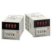
H5CN-YCN-AC100-240
Description
TIMER DIGITAL LED
Manufacturer
Omron
Datasheet
1.H5CN-XAN-AC100-240.pdf
(15 pages)
Specifications of H5CN-YCN-AC100-240
Rohs Compliant
YES
Supply Voltage Range
100VAC To 240VAC
Power Consumption
2.5W
Reset Time
20ms
Time Range
1s To 99min 59s


Connection of Load Circuit
Load 1 connected in series with NO contact (between terminals I
and K) is normally open, and the load circuit voltage will be applied
to it after the lapse of the set time. The load circuit voltage is normally
applied to load 2 connected in series with NC contact (between ter-
minals H and K), which will be open after the lapse of the set time.
4. Connection of Reset Input
Connection of the reset input contact or an open collector transistor
between terminals A and C (between terminals C and G for mod-
els with backup power for memory protection) permits the timer to
reset when contact is made or the transistor turns ON. Use of a high-
reliability gold-plated contact is recommended for the reset input. For
the reset input transistor, select the one satisfying the following elec-
trical ratings:
V
IC = 50 mA min.
I
V
Model without Backup Power for Memory
Protection
Model with Backup Power for Memory
Protection (H5CN-X@NM)
CEO
CEO
CE(sat)
(leakage current) = 0.5 µA max.
= 20 V min.
Note: The maximum load current is 3 A (resistive load).
(residual voltage) = 2 V max.
External
battery
Reset input
transistor
(Timer resets
when transistor
is ON.)
Reset input
transistor
(Timer resets
when transistor
is ON.)
Reset input
contact
(Timer resets
when contact is
made.)
Reset input
contact
(Timer resets
when contact is
made.)
External
battery
External
battery
Load 2
Load 1
Load circuit
voltage
(250 VAC,
30 VDC max.)
5. Connection of Gate Input
Connection of the gate input contact or an open collector transistor
between terminals A and D (between terminals C and E for mod-
els with backup power for memory protection) permits the timer to
stop operation while contact is made or the transistor turns ON. Use
of a high-reliability gold-plated contact is recommended for the gate
input. For the gate input transistor, select the one satisfying the fol-
lowing electrical ratings:
V
IC = 50 mA min.
I
V
Use a gate input contact with a short bounce time because the con-
tact bounce time causes an error in the operate time of the timer for a
period equalling the bounce time.
Model without Backup Power for Memory
Protection
Model with Backup Power for Memory
Protection (H5CN-X@NM)
6. Battery Connections when Using
Backup Power for Memory Protection
Always connect a battery when using models with backup power for
memory protection (H5CN-X@NM). Any 3-V battery can be used, but
the backup time will depend on the capacity of the battery.
When using the Unit for the first time after purchase, apply power
and reset the Unit once before using it. When power is turned ON for
the first time, outputs may be produced at the same time, so do not
connect the output terminals.
When connecting the battery using a Socket (P2CF-11 or P3GA-11),
check the terminal numbers on the Socket and connect the positive
side of the battery to terminal D and the negative side to terminal A.
CEO
CEO
CE(sat)
(leakage current) = 0.1 mA max.
= 20 V min.
(residual voltage) = 2 V max.
Gate input transistor
(Timer stops when
transistor is ON.)
Gate input transistor
(Timer stops when
transistor is ON.)
Gate input contact
(Timer stops when
contact is made.)
Gate input contact
(Timer stops when
contact is made.)
External
battery
External
battery
H5CN
8
Related parts for H5CN-YCN-AC100-240
Image
Part Number
Description
Manufacturer
Datasheet
Request
R


Part Number:
Description:
Digital Timer
Manufacturer:
Omron Corporation
Datasheet:
Part Number:
Description:
G6S-2GLow Signal Relay
Manufacturer:
Omron Corporation
Datasheet:
Part Number:
Description:
Compact, Low-cost, SSR Switching 5 to 20 A
Manufacturer:
Omron Corporation
Datasheet:
Part Number:
Description:
Manufacturer:
Omron Corporation
Datasheet:
Part Number:
Description:
Manufacturer:
Omron Corporation
Datasheet:
Part Number:
Description:
Manufacturer:
Omron Corporation
Datasheet:
Part Number:
Description:
Manufacturer:
Omron Corporation
Datasheet:
Part Number:
Description:
Manufacturer:
Omron Corporation
Datasheet:
Part Number:
Description:
Manufacturer:
Omron Corporation
Datasheet: