10-1412.1279 EAO, 10-1412.1279 Datasheet
10-1412.1279
Specifications of 10-1412.1279


Related parts for 10-1412.1279


10-1412.1279 Summary of contents
Page 1
... EAO – Your Expert Partner for Human Machine Interfaces EAO Product Information Series 44 ...
Page 2
...
Page 3
Switches and Indicators 44 ...
Page 4
Contents Description ...................................................................................................... 3 Product Assembly .......................................................................................... 4 Mounting instruction ...................................................................................... 5 Devices complete, raised mounting.............................................................. 6 Devices raised mounting ............................................................................. 12 Devices flush mounting ............................................................................... 27 Accessories................................................................................................... 38 Technical Data............................................................................................... 50 Typical Applications ..................................................................................... 52 Application guidelines.................................................................................. 53 Marking ...
Page 5
... Terminals All function elements have shockproof screw terminals (finger safety in accordance with DIN VDE 0106, part 100 and VBG 4) and have openings to guide a screwdriver. When delivered, the screw terminals are open, thus guaranteeing safe and fast installation. The lamp transformer has srew terminals as primary-terminal and as secondary connection connecting leads with multi-core cable ends ...
Page 6
Product Assembly Illuminated pushbutton, front mounting, raised mounting 0 Illuminated pushbutton, front mounting, flush mounting 0 Illuminated pushbutton, base mounting (separated mounting), raised mounting 0 4 03.2009 1 Actuator 2 Label for Label support 3 Label support 4 Fixing nut ...
Page 7
Mounting instruction Dismantling function elements To dismantle switching element, lamp element or lamp transformer, slightly lift the latching arm with the tip of a screwdriver. 0 > Mounting lamp transformer 0 Base adaptor Front adaptor Lamp transformer ...
Page 8
Devices complete, raised mounting Indicator full-face illumination complete Essential Accessories: d Single-LED page 45 Continuation see next page Indicator full-face illumination complete non-markable Terminals Screw terminal Mounting dimensions from page 58, Technical drawing from page 59, Circuit drawing ...
Page 9
... Plastic matt-chrome Plastic white 1 NO Plastic matt-chrome Plastic green Plastic yellow 44 Ø Typ-Nr. 44-702.20.100 0.037 44-702.25.010 0.030 44-701.22.001 0.030 44-701.20.100 0.037 44-701.25.010 0.030 44-701.29.010 0.030 44-701.24.010 0.030 Ø Typ-Nr. 44-747.29.100 0.047 44-747.25.010 0.040 44-746.22.001 0.040 44-746.29.100 0.047 44-746.25.010 0.040 44-746.24.010 0.040 7 03.2009 ...
Page 10
... Switching action Maintained action Contacts Normally closed Mounting dimensions from page 58, Technical drawing from page 59, Circuit drawing from page 73 8 03.2009 Mushroom had cap Plastic red Plastic red Mushroom had cap Plastic red 44 Ø Typ-Nr. 44-713.001 0.083 44-712.001 0.047 Ø Typ-Nr. 44-710.001 0.057 ...
Page 11
... Standard lock 9500 Terminals Screw terminal Switching action Maintained action Contacts Normally open Mounting dimensions from page 58, Technical drawing from page 59, Circuit drawing from page 73 Contacts Front ring Plastic matt-chrome 44-730.21.100 Plastic matt-chrome 44-730.22.100 Front ring MA-0- Plastic matt-chrome 44 Ø Typ-Nr ...
Page 12
... Contacts Normally open Mounting dimensions from page 58, Technical drawing from page 59, Circuit drawing from page 73 10 03.2009 Contacts Lever Front ring Plastic black Plastic matt-chrome Lever Front ring MA-0- Plastic black Plastic matt-chrome 44 Ø Typ-Nr. 44-720.20.100 0.045 Ø Typ-Nr. 44-724.20.020 0.048 ...
Page 13
... Caution! With flat receptacle, VDE 0630 and SEV standards specify use of insulating sleeve No. 280-0010-00. Terminals Soldering terminal (also pluggable 2.8 x 0.5 mm) Switching action Momentary action Contacts Normally closed Normally open ...
Page 14
Devices raised mounting Indicator actuator full-face illumination Essential Accessories: d Front adapter, front mounting page 42 d Lamp element, front mounting page 43 d Single-LED page 45 Continuation see next page Indicator actuator full-face illumination non-markable Mounting dimensions from page ...
Page 15
Devices raised mounting Indicator actuator front illumination Essential Accessories: d Base adaptor page 43 d Front adapter, front mounting page 42 d Lamp element, front mounting page 43 d Single-LED page 45 Continuation see next page Indicator actuator front illumination ...
Page 16
Devices raised mounting Pushbutton actuator Essential Accessories: d Base adaptor page 43 d Front adapter, front mounting page 42 d Slow-make switching element stackable, front mounting page 42 Continuation see next page Pushbutton actuator non-markable 14 03.2009 ...
Page 17
Devices raised mounting Continued from previous page non-markable level with bezel Switching elements max. Switching action Momentary action Maintained action Mounting dimensions from page 58, Technical drawing from page 59, ...
Page 18
Devices raised mounting Pushbutton actuator markable Essential Accessories: d Front adapter, front mounting page 42 d Marking plate for Lens page 38 d Slow-make switching element stackable, front mounting page 42 Continuation see next page Pushbutton actuator markable Colour of ...
Page 19
Devices raised mounting Illuminated pushbutton actuator Essential Accessories: d Front adapter, front mounting page 42 d Lamp element, front mounting page 43 d Single-LED page 45 d Slow-make switching element stackable, front mounting page 42 Continuation see next page Illuminated ...
Page 20
Devices raised mounting Double pushbutton actuator Essential Accessories: d Front adapter, front mounting page 42 d Lamp element, front mounting page 43 d Single-LED page 45 d Slow-make switching element stackable, front mounting page 42 Continuation see next page Double ...
Page 21
Devices raised mounting Emergency-stop pushbutton actuator, foolproof EN IEC 60947-5-5 Application as per DIN EN ISO 13850 and EN 60204-1 Essential Accessories: d Front adapter, front mounting page 42 d Slow-make switching element stackable, front mounting page 42 Continuation see ...
Page 22
... Terminals Screw terminal Switching action Maintained action Contacts Normally closed Normally open Technical drawing from page 59 20 03.2009 Mushroom had cap Plastic red Contacts Mushroom had cap Plastic 44 Ø Ø Typ-Nr. Typ-Nr. 44-710 0.040 44-711 0.035 Ø Lens Typ-Nr. red 44-001.4-03 44 0.234 ...
Page 23
Devices raised mounting Mushroom-head pushbutton actuator Essential Accessories: d Front adapter, front mounting page 42 d Slow-make switching element stackable, front mounting page 42 Continuation see next page Mushroom-head pushbutton actuator Switching action Momentary action Mounting dimensions from ...
Page 24
Devices raised mounting Keylock switch actuator 3 positions Essential Accessories: d Front adapter, front mounting page 42 d Slow-make switching element stackable, front mounting page 42 Continuation see next page 0 Keylock switch actuator 3 positions Position 0 : Basic ...
Page 25
Devices raised mounting Selector switch actuator 2 positions Essential Accessories: d Front adapter, front mounting page 42 d Slow-make switching element stackable, front mounting page 42 Continuation see next page 0 Selector switch actuator 2 positions Position 0 : Basic ...
Page 26
Devices raised mounting Selector switch actuator 3 positions Essential Accessories: d Front adapter, front mounting page 42 d Slow-make switching element stackable, front mounting page 42 Continuation see next page 0 Selector switch actuator 3 positions Position 0 : Basic ...
Page 27
Devices raised mounting Interlocking pushbutton actuator Essential Accessories: d Front adapter, front mounting page 42 d Slow-make switching element non-stackable, base mounting page 43 d Slow-make switching element stackable, front mounting page 42 Continuation see next page Interlocking pushbutton actuator ...
Page 28
... Devices raised mounting Potentiometer-drive Continuation see next page Potentiometer-drive Potentiometer 10 kΩ included others on request, resistance value as per IEC 63, series E3 without Potentiometer Specification for Potentiometer : Shaft = length 32 mm Shaft end = Form A Diameter = 6 mm Mounting dimensions from page 58, Technical drawing from page 59, Circuit drawing from page ...
Page 29
Devices flush mounting Indicator actuator full face illumination, flush mounting Essential Accessories: d Front adapter, front mounting page 42 d Front bezel set without label support, flush mounting page 38 d Lamp element, front mounting page 43 d Single-LED page ...
Page 30
Devices flush mounting Indicator actuator front illumination, flush mounting Essential Accessories: d Front adapter, front mounting page 42 d Front bezel set without label support, flush mounting page 38 d Lamp element, front mounting page 43 d Single-LED page 45 ...
Page 31
Devices flush mounting Pushbutton actuator, flush mounting Essential Accessories: d Front adapter, front mounting page 42 d Front bezel set without label support, flush mounting page 38 d Slow-make switching element stackable, front mounting page 42 Continuation see next page ...
Page 32
Devices flush mounting Continued from previous page non-markable Switching elements max. Switching action Momentary action Maintained action Mounting dimensions from page 58, Technical drawing from page 59, Circuit drawing from page ...
Page 33
Devices flush mounting Pushbutton actuator markable, flush mounting Essential Accessories: d Front adapter, front mounting page 42 d Front bezel set without label support, flush mounting page 38 d Marking plate for Lens page 38 d Slow-make switching element stackable, ...
Page 34
Devices flush mounting Illuminated pushbutton actuator, flush mounting Essential Accessories: d Front adapter, front mounting page 42 d Front bezel set without label support, flush mounting page 38 d Lamp element, front mounting page 43 d Single-LED page 45 d ...
Page 35
Devices flush mounting Keylock switch actuator 2 positions, flush mounting Essential Accessories: d Base adaptor page 43 d Front adapter, front mounting page 42 d Front bezel set without label support, flush mounting page 38 d Slow-make switching element stackable, ...
Page 36
Devices flush mounting Keylock switch actuator 3 positions, flush mounting Essential Accessories: d Front adapter, front mounting page 42 d Front bezel set without label support, flush mounting page 38 d Slow-make switching element stackable, front mounting page 42 Continuation ...
Page 37
Devices flush mounting Selector switch actuator 2 positions, flush mounting Essential Accessories: d Front adapter, front mounting page 42 d Front bezel set without label support, flush mounting page 38 d Slow-make switching element stackable, front mounting page 42 Continuation ...
Page 38
Devices flush mounting Selector switch actuator 3 positions, flush mounting Essential Accessories: d Front adapter, front mounting page 42 d Front bezel set without label support, flush mounting page 38 d Slow-make switching element stackable, front mounting page 42 Continuation ...
Page 39
... Potentiometer-drive, flush mounting Essential Accessories: d Front bezel set without label support, flush mounting page 38 Continuation see next page Potentiometer-drive, flush mounting Potentiometer 10 kΩ included others on request, resistance value as per IEC 63, series E3 without Potentiometer Specification for Potentiometer : Shaft = length 32 mm Shaft end = Form A ...
Page 40
... Typ-Nr. 44-966.6 0.001 44-966.7 0.001 44-966.5 0.001 44-966.2 0.001 44-966.4 0.001 e Typ-Nr. 44-962.9 0.001 44-961.0 0.001 44-961.6 0.001 44-961.5 0.001 44-961.2 0.001 44-961.4 0.001 Ø Typ-Nr. 44-965.6 0.003 44-965.7 0.003 44-965.5 0.003 44-965.2 0.003 44-965.4 0.003 e 43 0.010 43 0.006 ...
Page 41
Accessories Front bezel set with label support, flush mounting Continuation see next page Front bezel set with label support, flush mounting for Illuminated pushbutton and Pushbutton, Selector- and Keylock switch, Interlocking pushbutton the mounting depth extends for 12 mm for ...
Page 42
Accessories Label support with label Continuation see next page Label support with label 29.5 x 49.5 mm, plastic black, label unmarked, remove sealing ring from actuator 29.5 x 49.5 mm, plastic grey, label unmarked, remove sealing ring from actuator Technical ...
Page 43
Accessories Front protective cap Continuation see next page Front protective cap only in connection with flush Front ring. Protection when used under adverse ambient conditions. Remove gasket from the actuator. Cannot be used with the label support. Keylock cap Continuation ...
Page 44
... Slow-make switching element 500 VAC stackable, front mounting Forced opening as per EN IEC 947-5-1 overlapping, not to use with Emergecy- 500 VAC Hard silver stop switch Contacts Normally closed Normally open Contact material: Au/Ag = Gold/Silver Terminals Screw terminal Technical drawing from page 59, Circuit drawing from page ...
Page 45
... Continuation see next page Slow-make switching element non-stackable, base mounting Forced opening as per EN IEC 947-5-1 Contacts Normally open Normally closed Terminals Screw terminal Technical drawing from page 59, Circuit drawing from page 73 Switch rating 500 VAC Hard silver ST 500 VAC Hard silver ST ST ...
Page 46
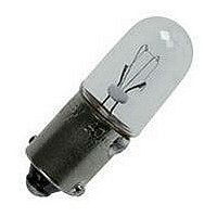
... The max. overall length of the lamp may not exeed 25 mm Continuation see next page Socket Filament lamp BA9s 44 03.2009 Typ-Nr. ST 44-525 Operating voltage/-current Typ-Nr. 110 VAC/DC 10-1422.1179 12 VAC/DC, 100 mA 10-1409.1329 130 VAC/DC 10-1424.1179 24 VAC/DC 10-1412.1279 36 VAC/DC 10-1416.1289 48 VAC/DC 10-1419.1249 6 VAC/DC, 200 mA 10-1406.1369 60 VAC/DC 10-1420.1219 0.011 e Typ-Nr. 44-940 6 0.008 e 0 ...
Page 47
... VAC 10-2H24.2059 0.002 230 VAC 10-2H25.2049 0.002 24 VAC/DC 10-2512.1149 28 VAC/DC 10-2513.1149 48 VAC/DC, 4/8 mA 10-2519.1059 6 VDC 10-2506.1089 12 VAC/DC 10-2509.1144 130 VAC 10-2H24.2054 0.002 230 VAC 10-2H25.2044 0.002 24 VAC/DC 10-2512.1144 28 VAC/DC 10-2513.1144 48 VAC/DC, 4/8 mA 10-2519.1054 6 VDC 10-2506.1084 44 e 0.002 0.002 0.002 ...
Page 48
... Lamp transformer Continuation see next page Lamp transformer Short-circuit proof, 1.2 VA, 50/60 Hz, for front or base mounting Terminals Screw terminal Technical drawing from page 59 46 03.2009 Operating voltage 1 D 220 ... 240 VAC 110 ... 125 VAC 220 ... 240 VAC 110 ... 125 VAC Operating voltage ...
Page 49
... V / 1.2 W 2.7 kΩ, for filament lamp 1.2 W 3.3 kΩ, for filament lamp 1.2 W 4.7 kΩ, for filament lamp 1 kΩ, for filament lamp 110 ... 130 V / 2.4 W Please keep to the country specific security rules. Terminal plate empty for fitting with series resistors ...
Page 50
Accessories Emergency-stop enclosures Colour yellow Continuation see next page Emergency-stop enclosures 1 Mounting hole, with adaptor for base mounting Technical drawing from page 59 Cable gland Continuation see next page Cable gland for Enclosure M20, with nut and sealing, fixing ...
Page 51
Accessories Cable gland Continuation see next page Cable gland for Enclosure M20, with nut and sealing, fixing area 7 ... 13 mm dia. Reducing ring Continuation see next page Reducing ring Aluminium natural, Mounting hole size 30.5 mm dia., 2 ...
Page 52
... EN IEC 60068-2-1 +60 °C, as per EN IEC 60068-2-2 Protection degree Actuators at front and enclosure IP 65, as per EN IEC 60529 Shock resistance 40 g (duration 6 ms), as per EN IEC 60 68-2-27 Vibration resistance sinusoidal 10-500 Hz, as per EN IEC 60068-2-6 44 imp e 6 switching operations minimal minimal ...
Page 53
... Mechanical lifetime 2 million cycles of operation Electrical characteristics Contact resistance New state with gold plated contact ≤50 mΩ, statically Electrical life >10 000 cycles of operation Switch rating as per EN IEC 61058-1 250 VAC cosφ 0.7 ... 0.8 250 VDC, 0.5 A 110 VDC VDC VAC/DC min ...
Page 54
... Only apply incandescent lamps with special data ! Incandescent lamp 130 V, 2.4 W, Typ-Nr. 10-1423.1179 Incandescent lamp 60 V, 1.2 W, Typ-Nr. 10-1420.1179 - Max. environmental temperature 40 °C for Resistor diode element Typ-Nr. 44-614.11 und 44-614.21 - For base mounting of the diode element Typ-Nr. 44612.2 the connection wire which just comes out in the middle must be placed so that it does not interfere with the actuator system ...
Page 55
Application guidelines Suppressor circuits When switching inductive loads such as relays, DC motors, and DC solenoids always important to absorb surges (e.g. with a diode) to protect the contacts. When these inductive loads are switched off, a counter ...
Page 56
... Marking Label marking for label support Label black anodized 0 Standard text Text-No OFF Down T 13 > Standard texts for marking plates and marking caps for Indicator and Illuminated Pushbutton Height of letters 03.2009 Standard text Text-No. Forwards T 14 Revers T 15 Right T 16 Left ...
Page 57
Marking > Symbols for marking plates and marking caps for Indicator and Illuminated Pushbutton 0 Continuation see next page > 03.2009 ...
Page 58
Marking Continued from previous page 0 56 03.2009 44 ...
Page 59
Drawings Component layout 1 Control switch page 11 2 Control switch page 11 3 Double pushbutton actuator page 18 Arrangement switching element designation of front adaptor 1 Switching action red (black) button pressed green (white) button pressed 4 Keylock switch ...
Page 60
... Key lock switch 2 positions complete page 9 | Key lock switch 3 positions complete page 9 | Selector switch 2 positions complete page 10 | Selector switch 3 positions complete page 10 | Indicator actuator full-face illumination page 12 | Indicator actuator front illumination page 13 | Pushbutton actuator page 14 | Pushbutton actuator markable page 16 | Illuminated ...
Page 61
Drawings 5 Indicator actuator full face illumination, flush mounting page 27 | Indicator actuator front illumination, flush mounting page 28 | Pushbutton actuator, flush mounting page 29 | Pushbutton actuator markable, flush mounting page 31 | Illuminated pushbutton actuator, flush ...
Page 62
Drawings 3 Resistor diode element page 46 | Diode element page 46 4 Lamp, base mounting page 44 5 Blind plug page 41 6 Blind element page 44 7 Label support without label page 39 | Label support with label ...
Page 63
... Drawings 8 Legend plate page 39 9 Protective cover page 40 10 Control switch page 03.2009 ...
Page 64
Drawings 11 Pushbutton actuator, flush mounting page 29 max. 35.95 Front bezel 1. level 2. level 62 03.2009 max. 35.95 Front bezel Fixing element with label support max Lens level with bezel lower than bezel max. ...
Page 65
Drawings 12 Indicator actuator full face illumination, flush mounting page 27 | Indicator actuator front illumination, flush mounting page 28 13 Indicator full-face illumination complete page 6 | Indicator front illumination complete page 03.2009 ...
Page 66
... Drawings 14 Pushbutton complete page 7 15 Illuminated pushbutton complete page 7 16 Selector switch 2 positions complete page 10 17 Selector switch 3 positions complete page 10 64 03.2009 44 ...
Page 67
Drawings 18 Key lock switch 2 positions complete page 9 19 Indicator actuator full-face illumination page 12 20 Pushbutton actuator page 14 max max level with bezel lower than bezel 21 Selector switch actuator 2 ...
Page 68
Drawings 22 Indicator actuator front illumination page 13 23 Pushbutton actuator markable page 16 24 Illuminated pushbutton actuator page 17 66 03.2009 44 ...
Page 69
Drawings 25 Pushbutton actuator markable, flush mounting page 31 | Illuminated pushbutton actuator, flush mounting page 32 26 Selector switch actuator 2 positions, flush mounting page 35 | Selector switch actuator 3 positions, flush mounting page 03.2009 ...
Page 70
Drawings 27 Key lock switch 3 positions complete page 9 28 Stop pushbutton, complete page 8 29 Emergency-stop pusbutton, foolproof EN IEC 60947-5-5, complete page 8 30 Keylock switch actuator 2 positions page 21 | Keylock switch actuator 3 positions ...
Page 71
Drawings 31 Mushroom-head pushbutton actuator page 21 32 Emergency-stop pushbutton actuator, foolproof EN IEC 60947-5-5 page 19 47 max Stop pushbutton actuator page 20 Switching element not stachable 47 max Switching element stachable 69 ...
Page 72
... Interlocking pushbutton actuator page 25 36 Double pushbutton actuator page 18 14 max. 6 29.5 1. level 2. level 70 03.2009 Mounting depth 1. level 2. level X [mm] 44-111/ max 44-121 44-111- max 44-162 44-131- 44-111/ max. 92 44-162 44-121 44-970- 44-131- max. 100 44-977 44-162 44-131- 44-131- max. 103 44-162 44-162 44 ...
Page 73
Drawings 37 Potentiometer-drive page 26 38 Interlocking pushbutton actuator, flush mounting page 37 39 Slow-make switching element stackable, front mounting page 42 | Slow-make switching element non-stachable, front mounting page 03.2009 ...
Page 74
Drawings 40 Lamp element, front mounting page 43 41 Slow-make switching element non-stackable, base mounting page 43 42 Lamp transformer page 46 43 Front bezel set without label support, flush mounting page 38 | Front bezel set with label support, ...
Page 75
Drawings 44 Emergency-stop enclosure page 19 | Stop pushbutton enclosure page 20 | Pushbutton enclosure page 25 | Emergency-stop enclosures page 48 | Enclosure page 48 Circuit drawing 1 Pushbutton actuator page 14 | Pushbutton actuator markable page 16 | ...
Page 76
... Selector switch actuator 2 positions page 23 | Selector switch actuator 2 positions, flush mounting page 35 15 Selector switch actuator 3 positions page 24 | Selector switch actuator 3 positions, flush mounting page 36 16 Selector switch actuator 3 positions page 24 | Selector switch actuator 3 positions, flush mounting page 36 17 Selector switch 2 positions complete page 10 74 03.2009 ...
Page 77
... Drawings 18 Selector switch 3 positions complete page 10 19 Interlocking pushbutton actuator page 25 | Interlocking pushbutton actuator, flush mounting page 37 20 Illuminated pushbutton actuator page 17 | Illuminated pushbutton actuator, flush mounting page 32 21 Pushbutton complete page 7 22 Illuminated pushbutton complete page 7 23 Pushbutton complete page 7 ...
Page 78
Drawings 27 Keylock switch actuator 2 positions page 21 | Keylock switch actuator 2 positions, flush mounting page 33 28 Keylock switch actuator 3 positions page 22 | Keylock switch actuator 3 positions, flush mounting page 34 29 Keylock switch ...
Page 79
Drawings 38 Slow-make switching element stackable, front mounting page 42 | Slow-make switching element non-stachable, front mounting page 43 | Slow-make switching element non-stackable, base mounting page 43 39 Slow-make switching element stackable, front mounting page 42 | Slow-make switching ...
Page 80
... Index from Typ-Nr. Typ-Nr. Page 10-1406.1369 .............................44 10-1409.1329 .............................44 10-1412.1279 .............................44 10-1416.1289 .............................44 10-1419.1249 .............................44 10-1420.1219 .............................44 10-1422.1179 .............................44 10-1424.1179 .............................44 10-2506.1082 .............................45 10-2506.1084 .............................45 10-2506.1085 .............................45 10-2506.1086 .............................45 10-2506.1089 .............................45 10-2509.1142 .............................45 10-2509.1144 .............................45 10-2509.1145 .............................45 10-2509.1146 .............................45 10-2509.1149 .............................45 10-2512.1142 .............................45 10-2512.1144 .............................45 10-2512.1145 .............................45 10-2512.1146 .............................45 10-2512.1149 .............................45 10-2513.1142 .............................45 10-2513.1144 .............................45 10-2513.1145 .............................45 10-2513.1146 .............................45 10-2513.1149 .............................45 10-2519.1052 .............................45 10-2519.1054 .............................45 10-2519.1055 .............................45 10-2519.1056 .............................45 10-2519.1059 .............................45 10-2H24.2052 .............................45 10-2H24.2054 .............................45 10-2H24.2055 .............................45 10-2H24 ...
Page 81
... 44-742.20 ................................... 37 44-742.22 ................................... 25 44-742.22 ................................... 37 44-742.62 ................................... 25 44-742.62 ................................... 37 44-742.68 ................................... 25 44-742.68 ................................... 37 44-744.20 ................................... 26 44-744.20 ................................... 37 44-744.60 ................................... 26 44-744.60 ................................... 37 44-745.20-10K1 ......................... 26 44-745.20-10K1 ......................... 37 44-745.60-10K1 ......................... 26 44-745.60-10K1 ......................... 37 44-746.22 ................................... 17 44-746.22 ................................... 32 44-746.22.001 .............................. 7 44-746.24 ................................... 17 44-746.24 ................................... 32 44-746.24.010 .............................. 7 44-746.25 ................................... 17 44-746.25 ................................... 32 44-746.25.010 .............................. 7 44-746.26 ................................... 17 44-746.26 ................................... 32 44-746.29 ................................... 17 44-746.29 ................................... 32 44-746.29.100 .............................. 7 44-746.62 ................................... 17 44-746.62 ................................... 32 44-746.64 ................................... 17 44-746.64 ................................... 32 44-746.65 ................................... 17 44-746.65 ................................... 32 44-746.66 ................................... 17 44-746.66 ................................... 32 44-746.69 ................................... 17 44-746.69 ................................... 32 44-747.22 ................................... 17 44-747.22 ................................... 32 44-747 ...
Page 82
... Typ-Nr. Page 44-961.6 .....................................38 44-962.9 .....................................38 44-963 ........................................48 44-965.2 .....................................38 44-965.4 .....................................38 44-965.5 .....................................38 44-965.6 .....................................38 44-965.7 .....................................38 44-966.2 .....................................38 44-966.4 .....................................38 44-966.5 .....................................38 44-966 ...
Page 83
...
Page 84
... Fax +41 62 388 95 55 E-mail sales.ech@eao.com United Kingdom Phone +44 1444 236 000 Fax +44 1444 236 641 E-mail sales.euk@eao.com USA Phone +1 203 877 4577 Fax +1 203 877 3694 E-mail sales.eus@eao.com Other Countries Phone +41 62 286 92 10 Fax +41 62 296 21 62 E-mail info@eao.com ...