10-2602.3174C EAO, 10-2602.3174C Datasheet - Page 3
10-2602.3174C
Manufacturer Part Number
10-2602.3174C
Description
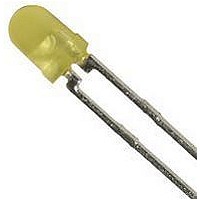
LED, T-1, YELLOW
Manufacturer
EAO
Datasheet
1.10-1613.1189.pdf
(20 pages)
Specifications of 10-2602.3174C
Bulb Size
T-1 (3mm)
Led Color
Yellow
Forward Current If
20mA
Forward Voltage
2.2V
Led Mounting
Through Hole
Lens Shape
Round
Mounting Type
Through Hole
No. Of Pins
2
Led Type
Standard
Lead Free Status / RoHS Status
Lead free / RoHS Compliant


Description
General Notes
The series 99 contains indicators and illuminated pushbuttons with
maintained and momentary action with one or two contacts which
may be either normally open or normally closed or a combination of
the two. The illuminated pushbuttons are equipped with the low-level
switching system.
The series 99 PCB keylock switch with a spacing of 19.05 mm com-
pletes the existing range of indicators and illuminated pushbuttons.
The PCB keylock switch is available with two and three positions,
with maintained action, and with either one or two normally open con-
tacts as well as with one normally open and one normally closed one.
Mounting
The illuminated pushbuttons of series 99 can be soldered to a printed
circuit board. The contact layout conforms to the module of 2.54 mm
(1/10“). A centering pin ensures dimensionally exact mounting in
rows or blocks.
With an M 1.2 screw the pushbuttons can also be fixed to a printed
circuit board. (This screw must be ordered separately.) The pushbut-
tons can be joined together easily with a coupling piece to form rows
or blocks.
The layout of the PCB keylock switch conforms to the module of 2.54
mm (1/10“).
Two centering pins ensure a dimensionally exact mounting. The con-
tact layout corresponds to that of series 99 switches.
Rules for cleaning soldered PC boards
In many cases the boards are cleaned following mechanical solde-
ring. In this case it is essential to prevent the cleaning fluid containing
dirt, grease and flux from entering the switch.
Lenses
The lens consists of a bezel, a marking plate and a transparent lens
plate, which may be either flat or concave.
Marking
For engraving, hot stamping and film inserts, see under “Markings”
on page 546.
Illumination
Illumination of the different coloured lenses is by lamps bipin T 1 lon-
glife (6-36 V) or LED bipin T 1.
Position indication
When a switch with maintained action is actuated, the lens remains
in the depressed position mechanically. The state of the switch is ap-
parent at all times from the position of the lens.
Keylock switch
standard lock (Index D)
10 different locks wit standard nos. 311-320. If the lock number is not
specified, we supply no. 311. Additional 125 locks, no. 321 - 445, are
available on request. Master keys for locks no. 311 - 445 may be
All dimensions in mm.
We reserve the right to modify technical data.
ordered by quoting no. 31-989.300.
Two keys are supplied with each keylock switch.
Spare keys for standard DOM locks may be ordered by quoting no.
31-989 (please state the lock number).
Number structure
99-XXX.8X7
99-9XX.X
99-9XX.X
Example:
Specimen order
Indicator single
- indicator single
Recommended accessories:
- lens single complete, flat
- LED, 1 chip, yellow
Contact material
Switch variant
Lens
Other accessories
-Illuminated pushbutton, single, with
momentary action; gold contact;
soldering terminals
99-455.837
-Lens, complette, flat
99-901.9
99-050.807
99-901.9
10-2602.3174C
01.2000
529
99
99
Related parts for 10-2602.3174C
Image
Part Number
Description
Manufacturer
Datasheet
Request
R

Part Number:
Description:
DIAL SCALE 10 TURN CONCENTRIC
Manufacturer:
Bourns Inc.
Datasheet:

Part Number:
Description:
Header Connector,PCB Mount,RECEPT,26 Contacts,PIN,0.1 Pitch,R ANGLE PC TAIL Terminal
Manufacturer:
Molex Inc
Datasheet:
Part Number:
Description:
Header Connector,PCB Mount,RECEPT,26 Contacts,PIN,0.1 Pitch,R ANGLE PC TAIL Terminal
Manufacturer:
Molex Inc
Datasheet:
Part Number:
Description:
BOARD-BOARD CONN, HEADER, 26WAY, 2ROW
Manufacturer:
Molex Inc
Datasheet:

Part Number:
Description:
BOARD-BOARD CONN, HEADER, 26WAY, 2ROW
Manufacturer:
Molex Inc
Datasheet:

Part Number:
Description:
Conn Circular PIN 26 POS Solder Cup ST Cable Mount 26 Terminal 1 Port
Manufacturer:
Amphenol
Datasheet:
Part Number:
Description:
Conn Circular SKT 26 POS Solder Cup ST Cable Mount 26 Terminal 1 Port
Manufacturer:
Amphenol
Datasheet:
Part Number:
Description:
Conn Circular PIN 26 POS Solder Cup ST Cable Mount 26 Terminal 1 Port
Manufacturer:
Amphenol
Datasheet:
Part Number:
Description:
Conn Circular SKT 26 POS Solder Cup ST Cable Mount 26 Terminal 1 Port
Manufacturer:
Amphenol
Datasheet:
Part Number:
Description:
Conn Circular PIN 26 POS Solder Cup ST Cable Mount 26 Terminal 1 Port
Manufacturer:
Amphenol
Datasheet:

Part Number:
Description:
SINGLE CHIP LED/ T1 BI-PIN/ 2.1VDC/20MA - RED
Manufacturer:
EAO
Datasheet:

Part Number:
Description:
CRIMP HOUSING, 0.2", 10WAY
Manufacturer:
Molex Inc
Datasheet:

Part Number:
Description:
CONN HOUSING 5POS .100 HI PRESS
Manufacturer:
Molex Inc
Datasheet:

Part Number:
Description:
CONN HOUSING 2POS 5.08MM
Manufacturer:
Molex Inc
Datasheet:

Part Number:
Description:
CONN HEADER 2POS .084 VERT TIN
Manufacturer:
Molex Inc
Datasheet: