TCST1202 Vishay, TCST1202 Datasheet - Page 3
TCST1202
Manufacturer Part Number
TCST1202
Description
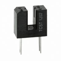
Optical Sensor (Switch) Transmissive / Slotted Interrupter
Manufacturer
Vishay
Type
Unamplifiedr
Datasheet
1.TCST1202.pdf
(7 pages)
Specifications of TCST1202
No. Of Channels
1
Optocoupler Output Type
Phototransistor
Input Current
60mA
Output Voltage
70V
Opto Case Style
Through Hole
No. Of Pins
4
Sensing Distance
0.122" (3.1mm)
Sensing Method
Transmissive
Output Configuration
Phototransistor
Current - Dc Forward (if)
60mA
Current - Collector (ic) (max)
200mA
Voltage - Collector Emitter Breakdown (max)
70V
Response Time
10µs, 8µs
Mounting Type
Through Hole
Package / Case
PCB Mount
Operating Temperature
-55°C ~ 85°C
Maximum Operating Temperature
+ 85 C
Minimum Operating Temperature
- 55 C
Wavelength
950 nm
Output Collector Emitter Voltage (detector)
70 V
Maximum Reverse Voltage (emitter)
6 V
Maximum Collector Current (detector)
2 mA (Typ)
Slot Width
3.1 mm
Aperture Width
0.5 mm
Output Device
Phototransistor
Power Dissipation
250 mW
Lead Free Status / RoHS Status
Lead free / RoHS Compliant
Lead Free Status / RoHS Status
Lead free / RoHS Compliant, Lead free / RoHS Compliant
Other names
751-1035-5
Available stocks
Company
Part Number
Manufacturer
Quantity
Price
Company:

Part Number:
TCST1202
Manufacturer:
Vishay Semiconductors
Quantity:
5 729
Company:
Part Number:
TCST1202
Manufacturer:
SHARP
Quantity:
20 000


Note
(1)
BASIC CHARACTERISTICS
T
Document Number: 83764
Rev. 1.9, 17-Aug-09
amb
BASIC CHARACTERISTICS
PARAMETER
INPUT (EMITTER)
Forward voltage
Junction capacitance
OUTPUT (DETECTOR)
Collector emitter voltage
Emitter collector voltage
Collector dark current
SWITCHING CHARACTERISTICS
Turn-on time
Turn-off time
T
amb
96 11862
= 25 °C, unless otherwise specified
R
t
T
= 25 °C, unless otherwise specified
t
p
0
20688
p
G
= 1 ms
1000
= 20
= 50 Ω
Fig. 4 - Forward Current vs. Forward Voltage
100
0.1
10
1
0
I
F
Fig. 2 - Test Circuit for t
0.2
50 Ω
I
F
0.4
V
F
0.6
- Forward Voltage (V)
100 Ω
0.8
1.0
V
+ 5 V
I
CE
R
R
C
Channel I
Channel II
1.2
For technical questions, contact:
L
L
I
I
= 25 V, I
V
on
TEST CONDITION
C
= 100 Ω (see figure 2)
C
= 100 Ω (see figure 2)
R
1.4
adjusted by I
= 2 mA, V
= 2 mA, V
and t
(1)
= 0 V, f = 1 MHz
I
I
F
I
E
C
1.6
Transmissive Optical Sensor with
= 60 mA
= 10 µA
= 1 mA
off
F
1.8
= 0 A, E = 0 lx
Oscilloscope
R
C
F
S
S
L
L
2.0
Phototransistor Output
= 5 V,
= 5 V,
≥ 1 MΩ
≤ 20 pF
PART
sensorstechsupport@vishay.com
TCST1103, TCST1202, TCST1300
Fig. 5 - Relative Current Transfer Ratio vs. Ambient Temperature
t
t
t
t
p
d
r
on
SYMBOL
(= t
100 %
V
V
95 11089
I
10 %
90 %
CEO
V
t
t
CEO
ECO
d
C
on
off
+ t
F
I
I
2.0
1.5
1.0
0.5
j
C
F
0
0
r
0
)
- 25
V
I
t
Pulse duration
Delay time
Rise time
Turn-on time
F
d
CE
t
on
= 20 mA
t
Fig. 3 - Switching Times
MIN.
T
r
= 5 V
70
amb
7
0
Vishay Semiconductors
t
- Ambient Temperature (°C)
p
25
TYP.
1.25
50
10
8
t
t
t
t
s
off
f
s
50
(= t
s
t
off
+ t
t
f
f
)
MAX.
75
100
1.6
Storage time
Fall time
Turn-off time
www.vishay.com
100
96 11698
t
t
UNIT
pF
nA
µs
µs
V
V
V
3
Related parts for TCST1202
Image
Part Number
Description
Manufacturer
Datasheet
Request
R

Part Number:
Description:
357-036-542-201 CARDEDGE 36POS DL .156 BLK LOPRO
Manufacturer:
Vishay
Datasheet:
Part Number:
Description:
357-036-542-201 CARDEDGE 36POS DL .156 BLK LOPRO
Manufacturer:
Vishay
Datasheet:
Part Number:
Description:
357-036-542-201 CARDEDGE 36POS DL .156 BLK LOPRO
Manufacturer:
Vishay
Datasheet:
Part Number:
Description:
357-036-542-201 CARDEDGE 36POS DL .156 BLK LOPRO
Manufacturer:
Vishay
Datasheet:
Part Number:
Description:
357-036-542-201 CARDEDGE 36POS DL .156 BLK LOPRO
Manufacturer:
Vishay
Datasheet:
Part Number:
Description:
357-036-542-201 CARDEDGE 36POS DL .156 BLK LOPRO
Manufacturer:
Vishay
Datasheet:
Part Number:
Description:
357-036-542-201 CARDEDGE 36POS DL .156 BLK LOPRO
Manufacturer:
Vishay
Datasheet:
Part Number:
Description:
357-036-542-201 CARDEDGE 36POS DL .156 BLK LOPRO
Manufacturer:
Vishay
Datasheet:
Part Number:
Description:
357-036-542-201 CARDEDGE 36POS DL .156 BLK LOPRO
Manufacturer:
Vishay
Datasheet:
Part Number:
Description:
357-036-542-201 CARDEDGE 36POS DL .156 BLK LOPRO
Manufacturer:
Vishay
Datasheet:
Part Number:
Description:
357-036-542-201 CARDEDGE 36POS DL .156 BLK LOPRO
Manufacturer:
Vishay
Datasheet:
Part Number:
Description:
357-036-542-201 CARDEDGE 36POS DL .156 BLK LOPRO
Manufacturer:
Vishay
Datasheet:
Part Number:
Description:
357-036-542-201 CARDEDGE 36POS DL .156 BLK LOPRO
Manufacturer:
Vishay
Datasheet:
Part Number:
Description:
357-036-542-201 CARDEDGE 36POS DL .156 BLK LOPRO
Manufacturer:
Vishay
Datasheet:
Part Number:
Description:
357-036-542-201 CARDEDGE 36POS DL .156 BLK LOPRO
Manufacturer:
Vishay
Datasheet: