TCLT1109 Vishay, TCLT1109 Datasheet - Page 4
TCLT1109
Manufacturer Part Number
TCLT1109
Description
OPTOCOUPLER, TRANSISTOR, 5000VRMS
Manufacturer
Vishay
Specifications of TCLT1109
No. Of Channels
1
Optocoupler Output Type
Phototransistor
Input Current
50mA
Output Voltage
70V
Opto Case Style
SOP
No. Of Pins
5
Propagation Delay
3µs
Isolation Voltage
5kV
Number Of Channels
1
Input Type
DC
Voltage - Isolation
5000Vrms
Current Transfer Ratio (min)
200% @ 5mA
Current Transfer Ratio (max)
400% @ 5mA
Voltage - Output
70V
Current - Output / Channel
50mA
Current - Dc Forward (if)
60mA
Vce Saturation (max)
300mV
Output Type
Transistor with Base
Mounting Type
Surface Mount
Package / Case
6-SOP (5 Leads)
Maximum Input Diode Current
60 mA
Maximum Reverse Diode Voltage
6 V
Output Device
Transistor With Base
Configuration
1
Maximum Collector Emitter Voltage
70 V
Maximum Collector Emitter Saturation Voltage
300 mV
Current Transfer Ratio
400 %
Maximum Forward Diode Voltage
1.6 V
Maximum Collector Current
50 mA
Maximum Power Dissipation
250 mW
Maximum Operating Temperature
+ 100 C
Minimum Operating Temperature
- 40 C
Approval Bodies
BSI, DIN & FIMKO
Rohs Compliant
Yes
Lead Free Status / RoHS Status
Lead free / RoHS Compliant
Lead Free Status / RoHS Status
Lead free / RoHS Compliant, Lead free / RoHS Compliant
Available stocks
Company
Part Number
Manufacturer
Quantity
Price

Part Number:
TCLT1109
Manufacturer:
VISHAY/威世
Quantity:
20 000


TCLT11..Series
Vishay Semiconductors
www.vishay.com
4
SWITCHING CHARACTERISTICS
PARAMETER
Delay time
Rise time
Turn-on time
Storage time
Fall time
Turn-off time
Turn-on time
Turn-off time
95 10804
94 9182
0
R
t
T
p
t
p
Fig. 3 - Test Circuit, Non-Saturated Operation
G
= 0.01
= 50 µs
= 50
300
250
200
150
100
50
I
0
F
0
50
Fig. 1 - Derating Diagram
I
F
T
25
si
- Safety Temperature (°C)
IR-Diode
I
100
si
50
(mA)
P
Phototransistor
V
V
V
V
V
V
si
V
V
75
+ 5 V
(mW)
S
S
S
S
S
S
S
S
I
For technical questions, contact: optocoupler.answers@vishay.com
Channel II
C
Channel I
= 5 V, I
= 5 V, I
= 5 V, I
= 5 V, I
= 5 V, I
= 5 V, I
= 5 V, I
= 5 V, I
= 2 mA; adjusted through
100
TEST CONDITION
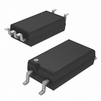
Optocoupler, Phototransistor Output,
SOP-6L5, Half Pitch, Long Mini-Flat
(see figure 3)
(see figure 3)
(see figure 3)
(see figure 3)
(see figure 3)
(see figure 3)
(see figure 4)
(see figure 4)
C
C
C
C
C
C
F
F
input amplitude
125
= 2 mA, R
= 2 mA, R
= 2 mA, R
= 2 mA, R
= 2 mA, R
= 2 mA, R
= 10 mA, R
= 10 mA, R
Oscilloscope
R
C
L
L
= 1 M
= 20 pF
150
L
L
L
L
L
L
L
L
= 100 Ω,
= 100 Ω,
= 100 Ω,
= 100 Ω,
= 100 Ω,
= 100 Ω,
= 1 kΩ,
= 1 kΩ,
Package
SYMBOL
t
t
t
t
t
t
t
on
t
off
on
off
DIN EN 60747-5-2(VDE 0884)/DIN EN 60747-; IEC 60747
d
s
Fig. 2 - Test Pulse Diagram for Sample Test According to
r
f
95 10843
0
R
t
T
p
t
13930
V
G
p
V
V
= 0.01
IOWM
= 50 µs
= 50 Ω
IOTM
IORM
V
Pd
I
0
Fig. 4 - Test Circuit, Saturated Operation
F
50 Ω
t
1
I
F
MIN.
= 10 mA
t
t
t
1 kΩ
1
3
stres
t
, t
test
, t
2
4
t
Tr
= 1 to 10 s
= 1 s
= 10 s
= 12 s
= 60 s
TYP.
10.0
3.0
3.0
6.0
0.3
4.7
5.0
9.0
+ 5 V
I
Channel II
Channel I
C
Document Number: 83514
MAX.
Rev. 2.1, 09-Jan-08
t
Oscilloscope
R
C
2
L
L
t
3
≤
≥
t
t
test
stres
1 MΩ
20 pF
t
t
4
UNIT
µs
µs
µs
µs
µs
µs
µs
µs
Related parts for TCLT1109
Image
Part Number
Description
Manufacturer
Datasheet
Request
R

Part Number:
Description:
Optocoupler/ Phototransistor Output/ SOP-6L5/ Half Pitch/ Long Mini-Flat Package
Manufacturer:
Vishay Siliconix
Datasheet:

Part Number:
Description:
357-036-542-201 CARDEDGE 36POS DL .156 BLK LOPRO
Manufacturer:
Vishay
Datasheet:
Part Number:
Description:
357-036-542-201 CARDEDGE 36POS DL .156 BLK LOPRO
Manufacturer:
Vishay
Datasheet:
Part Number:
Description:
357-036-542-201 CARDEDGE 36POS DL .156 BLK LOPRO
Manufacturer:
Vishay
Datasheet:
Part Number:
Description:
357-036-542-201 CARDEDGE 36POS DL .156 BLK LOPRO
Manufacturer:
Vishay
Datasheet:
Part Number:
Description:
357-036-542-201 CARDEDGE 36POS DL .156 BLK LOPRO
Manufacturer:
Vishay
Datasheet:
Part Number:
Description:
357-036-542-201 CARDEDGE 36POS DL .156 BLK LOPRO
Manufacturer:
Vishay
Datasheet:
Part Number:
Description:
357-036-542-201 CARDEDGE 36POS DL .156 BLK LOPRO
Manufacturer:
Vishay
Datasheet:
Part Number:
Description:
357-036-542-201 CARDEDGE 36POS DL .156 BLK LOPRO
Manufacturer:
Vishay
Datasheet:
Part Number:
Description:
357-036-542-201 CARDEDGE 36POS DL .156 BLK LOPRO
Manufacturer:
Vishay
Datasheet:
Part Number:
Description:
357-036-542-201 CARDEDGE 36POS DL .156 BLK LOPRO
Manufacturer:
Vishay
Datasheet:
Part Number:
Description:
357-036-542-201 CARDEDGE 36POS DL .156 BLK LOPRO
Manufacturer:
Vishay
Datasheet:
Part Number:
Description:
357-036-542-201 CARDEDGE 36POS DL .156 BLK LOPRO
Manufacturer:
Vishay
Datasheet:
Part Number:
Description:
357-036-542-201 CARDEDGE 36POS DL .156 BLK LOPRO
Manufacturer:
Vishay
Datasheet:
Part Number:
Description:
357-036-542-201 CARDEDGE 36POS DL .156 BLK LOPRO
Manufacturer:
Vishay
Datasheet: