HFBR-5103T Avago Technologies US Inc., HFBR-5103T Datasheet - Page 2
HFBR-5103T
Manufacturer Part Number
HFBR-5103T
Description
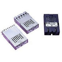
Fiber Optics, Transceiver Module
Manufacturer
Avago Technologies US Inc.
Datasheet
1.HFBR-5103T.pdf
(4 pages)
Specifications of HFBR-5103T
Peak Reflow Compatible (260 C)
No
Leaded Process Compatible
No
Lead Free Status / RoHS Status
Contains lead / RoHS non-compliant


2. Mechanical and Environmental Tests
2. Mechanical and Environmental Tests (continued)
Test
Temp. Cycle
85/85 Biased
Mechanical Shock
Mechanical Vibration
Wave Soldering
Test
Hand Soldering and
Resistance to
Solvents
Lead/Terminal
Strength
Solder Post
Pullout
Side Load
2
Conditions
-40 C to 100 C,
15 min. dwell, 5 min. transfer
T
V
See note 1
MIL-STD-883 Method 2002B,
1,500 g, 6 Directions
MIL-STD-883 Method 2007A
20-2000 Hz, 20g
2 sec. on 260 C Solder; 5 min.
Wash in 60-70 C DI water under
40 psi; 20 min. Bake @ 70 C
Conditions
315 C-10 sec. Hand Soldering,
followed by Resistance to
Solvents per MIL-STD-883,
Method 2015.7
MIL-STD-883, Method 2004.5.
1 kg tensile pull for 10 sec. /
1 kg bending pull for 3 sec.
at 30 deg.
Lift housing from PCB
and measure “break” force
With connector inserted, each
D.U.T. was pulled (on the
connector) to the Right and then
to the Left with 10 lb force and
held for 60 sec. per Digital
A-PS2400001-GS, section 3.1.8
A
CC
= 85 C, 85% RH,
= +5.25 V.
Duration
2000 cycles
1,000 hours
3 Times
Duration
1 kg tensile pull
applied to
each lead for 10 sec.,
then bend lead 30
while under pull for
3 sec., 3 bendings
each lead.
Each transceiver
received 6 pulls,
3 on the right
and 3 on the left
(Testing done on a constructional basis)
Sample Size
22
11
5
5
65
Sample Size
5
(HFBR-5207)
10
(HFBR-5103)
2
(HFBR-5103T) Max. force: >10 kg
4
(HFBR-5208)
Failure
Results
0
0
0
0
0
0
0
Min. force: 4 kg
0
(continues)
Related parts for HFBR-5103T
Image
Part Number
Description
Manufacturer
Datasheet
Request
R

Part Number:
Description:
RECEIVER FIBER OPTIC 600NM 40KBD
Manufacturer:
Avago Technologies US Inc.
Datasheet:

Part Number:
Description:
XMITTER FIBER OPTIC 600NM 5MBD
Manufacturer:
Avago Technologies US Inc.
Datasheet:

Part Number:
Description:
XMITTER FIBER OPTIC 600NM 40KBD
Manufacturer:
Avago Technologies US Inc.
Datasheet:

Part Number:
Description:
XMITTER VERSATILE LINK HORZ
Manufacturer:
Avago Technologies US Inc.
Datasheet:

Part Number:
Description:
XMITTER OPT HI PERFORMANCE VERT
Manufacturer:
Avago Technologies US Inc.
Datasheet:

Part Number:
Description:
TXRX FIBER OPTIC 650NM 10MBAUD
Manufacturer:
Avago Technologies US Inc.
Datasheet:
Part Number:
Description:
TXRX FIBER OPTIC 650NM 10MBAUD
Manufacturer:
Avago Technologies US Inc.
Datasheet:

Part Number:
Description:
FIBER OPTIC TRANSMITTER 660NM
Manufacturer:
Avago Technologies US Inc.
Datasheet:

Part Number:
Description:
KIT EVAL FIBER OPTIC 5MBD
Manufacturer:
Avago Technologies US Inc.
Datasheet:
Part Number:
Description:
KIT EVAL FIBER OPTICS 32MBD
Manufacturer:
Avago Technologies US Inc.
Datasheet:

Part Number:
Description:
KIT EVAL FIBER OPTIC 5MBD
Manufacturer:
Avago Technologies US Inc.
Datasheet:

Part Number:
Description:
125MBd 1300nm FiberOptic Eval Kit
Manufacturer:
Avago Technologies US Inc.
Datasheet:

Part Number:
Description:
DC-5MBd 820nm FiberOptic EvalKit
Manufacturer:
Avago Technologies US Inc.
Datasheet:
Part Number:
Description:
125MBd 820nm FiberOptic Eval Kit
Manufacturer:
Avago Technologies US Inc.
Datasheet:
Part Number:
Description:
DC-5MBd 650nm POF Eval Kit
Manufacturer:
Avago Technologies US Inc.
Datasheet: