M20-ANT RF Solutions, M20-ANT Datasheet - Page 10
M20-ANT
Manufacturer Part Number
M20-ANT
Description
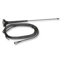
ANTENNA, MAESTRO 20
Manufacturer
RF Solutions
Datasheet
1.M20-ANT.pdf
(26 pages)
Specifications of M20-ANT
Svhc
No SVHC (15-Dec-2010)


DS020-7 Oct ‘06
2.4 Connect the modem to external device
You can use the optional ‘Y’ cable to connect the modem’s Sub-D connector to external controller/computer. Note :
The modem CANNOT be connected to the ‘Line’ jack of a landline telephone directly.
Connection example using optional ‘Y’ cable:
2.5 Connecting the DC power supply
Connect the open ending of the included power cord to a DC supply. Refer to the following for power supply
requirement.
Connect the connector to the modem. The modem will turn on automatically.
The status indicator on the modem will be lit when power on. After a few seconds it will go flashing slowly
(registered to the network successfully, refer section 1.2.1).
Chapter 3 describes how to communicate with the modem in Microsoft Windows
M
M
M
M
a
a
e
a
e
a
s
e
s
e
t
t
s
s
r
r
t
t
o
o
r
r
o
o
Rated current
1
1
0
2
0
2
0
0
0
0
/
/
Input voltage range
GSM100 U
S
S
©2006 REG No 277 4001, ENGLAND.
u
u
c
c
b
b
o
o
-
n
-
n
D
D
n
n
e
e
1
1
c
c
5
5
t
t
o
o
p
p
r
r
i
i
n
n
SERS
M
S
S
o
o
e
e
ANUAL
l
l
n
n
c
d
d
c
d
d
o
o
e
e
i
i
D
n
D
n
r
r
n
n
4
4
n
n
w
g
p
p
B
w
g
B
p
p
e
e
l
s
l
s
-
i
i
u
-
4
u
4
r
c
r
9
9
c
e
e
g
c
c
g
t
t
o
o
5V – 32V
r
r
650mA
A
A
(
(
C
C
n
n
-
o
o
o
-
o
D
D
t
r
r
t
C
C
i
i
b
b
n
n
a
a
c
c
A
TM
A
t
t
l
l
t
t
u
u
d
Page 10
d
e
e
d
d
a
a
r
r
e
environment.
y
y
e
p
p
d
d
t
t
o
o
)
)
r
r
H
H
R
R
a
a
S
S
n
n
-
-
d
2
d
2
s
s
3
3
e
e
2
2
t
t
p
p
o
o
o
o
f
f
r
r
p
p
t
t
h
h
o
o
o
o
f
f
n
n
P
P
e
e
C
C
Related parts for M20-ANT
Image
Part Number
Description
Manufacturer
Datasheet
Request
R

Part Number:
Description:
MOUNT, DIN RAIL
Manufacturer:
RF Solutions
Datasheet:

Part Number:
Description:
RF Switch SPDT 0MHz to 2GHz 27dB 8-Pin SOIC T/R
Manufacturer:
M/A-Com Technology Solutions
Datasheet:
Part Number:
Description:
RF Switch SPST 500MHz to 2GHz 40dB 8-Pin SOIC T/R
Manufacturer:
M/A-Com Technology Solutions
Datasheet:

Part Number:
Description:
RF Switch SPDT 100MHz to 4GHz 14dB 6-Pin SOT-6
Manufacturer:
Skyworks Solutions Inc
Datasheet:

Part Number:
Description:
IC ENCODER TRANSMITTER RF 8DIP
Manufacturer:
RF Solutions
Datasheet:

Part Number:
Description:
IC DECODER RECEIVER RF 18DIP
Manufacturer:
RF Solutions
Datasheet:

Part Number:
Description:
IC ENCODER 3 DGTL I/O SOT23-6
Manufacturer:
RF Solutions
Datasheet:

Part Number:
Description:
IC ENCODER 3 DGTL I/O 8-PDIP
Manufacturer:
RF Solutions
Datasheet:

Part Number:
Description:
IC DECODER 3 DGTL I/O 8-PDIP
Manufacturer:
RF Solutions
Datasheet:

Part Number:
Description:
IC DECODER 3 DGTL I/O 8-SOIC
Manufacturer:
RF Solutions
Datasheet:

Part Number:
Description:
118 SERIES AM REMOTE CONTROL SYSTEMS.
Manufacturer:
RF Solutions Ltd.