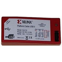
HW-USB-IIG Xilinx Inc, HW-USB-IIG Datasheet - Page 9

HW-USB-IIG
Manufacturer Part Number
HW-USB-IIG
Description
IC CABLE
Manufacturer
Xilinx Inc
Datasheet
1.HW-USB-II-G.pdf
(35 pages)
Specifications of HW-USB-IIG
Supply Voltage
5.25V
Accessory Type
Platform Cable USB II
Ic Cable Type
Download Cable
Connector Type B
USB A Plug
Connector Type A
2-mm Shrouded Keyed Socket
Silicon Family Name
Virtex II, Spartan II
Core Architecture
FPGA
Core Sub-architecture
Virtex, Spartan, XC4000
Rohs Compliant
Yes
Lead Free Status / RoHS Status
Lead free / RoHS Compliant
iMPACT Cable Status Bar
A status bar on the bottom edge of the iMPACT GUI
example, if the host port is USB 2.0, Platform Cable USB II connects at Hi-Speed and the status bar shows usb-hs. If the
host port is USB 1.1, Platform Cable USB II connects at full-speed, and the status bar shows usb-fs. Finally, the status bar
displays the active cable and TCK_CCLK_SCK frequency.
X-Ref Target - Figure 7
Status Indicator
Platform Cable USB II uses a tri-color status LED to indicate the presence of target voltage and to indicate that a cable
firmware update is in progress
When the cable is connected (using a ribbon cable, or flying leads) to a mating connector on the target system, the status
LED is illuminated as a function of the voltage present on pin 2 (V
attached to a voltage plane suppling the JTAG, SPI, or Slave Serial pins on the target device(s). Some devices have
separate power pins for this purpose (V
TMS, TDI, and TDO). Refer to the target device data sheet for details on JTAG, Slave Serial or SPI pins.
The status LED is amber when any one or more of the following conditions exist:
•
•
•
The status LED is green when all of the following conditions exist:
•
•
•
Note:
turn green until V
The status LED is red whenever a cable firmware update is in progress.
DS593 (v1.2.1) March 17, 2011
The cable is not connected to a target system
The target system is not powered
The voltage on the V
The cable is connected to a target system
The target system is powered
The voltage on the V
There is 200 mV of hysteresis in the V
REF
is raised above 1.5V.
REF
REF
pin is ≤ +1.3V.
pin is
(Figure
≥
+1.5V.
8).
Figure 7: iMPACT (10.1) Cable Status Bar
AUX
REF
), while others have a common supply for both V
detection circuit. If V
(Figure
www.xilinx.com
7) provides information about cable operating conditions. For
REF
REF
drops below 1.3V, the status LED turns amber and does not
). Users must design their system hardware with pin 2
CCIO
DS593_07_021908
and the JTAG pins (TCK,
Platform Cable USB II
9


