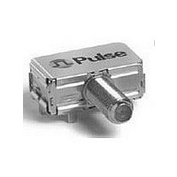
B5004 PULSE ELECTRONICS CORPORATION, B5004 Datasheet

B5004
Manufacturer Part Number
B5004
Description
Signal Conditioning FILTER MOD
Manufacturer
PULSE ELECTRONICS CORPORATION
Type
Cable modem low pass transmit filtersr
Datasheet
1.B5004.pdf
(2 pages)
Specifications of B5004
Rad Hardened
No
Impedance
75 Ohms
Operating Temperature Range
- 40 C to + 85 C
Lead Free Status / RoHS Status
Not Compliant
Broadband: RF & Wireless
BROADBAND: RF & WIRELESS
*NOTE: RoHS compliant versions of some of the products offered in this section are available. For more information, call and ask for
“Broadband RF and Wireless Applications. ” Local telephone numbers are on the back cover of this catalog. Or, you can send an e-mail to
1. SOIC = 50 mil pitch lead spacing
2. NL = Lead-free
48
1. Low Pass Port / High Pass Port
2. Leadless
3. Coaxial F-connector integrated
Number
Number
Number
A6801
A6802
PE-65507NL
PE-65508NL
CX6006L
CX6006
CX6008
C6026
CX6026
C6039
CX6007
C6035
CX6002
CX6020
C6001
C6001L
SF9023
C6036NL
C6086NL
SMT - Surface Mount Package
prodinfo_telecom@pulseeng.com.
B5004
B5005
C5001
C5003
C5005
CX5013
C5002
Part
Part
Part
3
3
4
2
3, 5
3, 5
Impedance
2
2
In/Out
5-65 / 85-870
5-65 / 85-870
5-65 / 85-864
5-44 / 58-860
5-44 / 58-860
5-860 / 975-1525
5-42 / 88-864
5-42 / 88-860
5-42 / 54-864
5-42 / 54-864
5-42 / 52-870
5-42 / 52-870
5-42 / 52-750
10-55 / 90-770
5-65 / 108-860
150 Ω
Dual Serial Data Interface Transformers
Frequency
1CT:1CT
150Ω
75 Ω
75 Ω
75 Ω
75 Ω
50 Ω
Turns
Ratio
(MHz)
1:1
1:1
1:1
FIBRE CHANNEL (SAN)
Passband
1
(MHz)
1-59.5
THT - Through Hole Package
5-42
5-65
1-50
1-80
1-65
1-49
Low Pass Filters
Insertion Loss
Diplex Filters
16-pin SOIC
16-pin SOIC
16-pin SOIC
16-pin SOIC
Style
1.0 TYP
<2.0
<1.2
<1.2
<1.5
<1.5
<1.0
<1.5
<1.5
<1.5
<1.0
<1.0
<1.5
<1.5
<1.5
Pulse offers a comprehensive line of RF magnetic components for use in wireless and RF applications,
including mobile communications, cable television, hybrid fiber/coax (HFC) equipment, cable modems,
(dB)
Insertion Loss Return Loss
1
(dB MAX)
4. L = Low cost
5. NL = Lead-free
Package
1.0
1.0
1.2
1.2
1.0
1.5
1.0
.500 / .295 / .220
.500 / .295 / .220
.500 / .270 / .220
.500 / .270 / .220
ease the development and manufacturing of today’s RF network equipment.
Return Loss
16 or better
18 or better
12 or better
12 or better
14 or better
12 or better
20 or better
20 or better
18 or better
12 or better
12 or better
L/W/H (in.)
10 or better
14 / 9
14 / 9
14 / 9
and through hole components have minimal insertion loss and excellent return loss to
(dB)
(dB MIN)
RF, HFC & CATV APPLICATIONS
1
1
1
diplex filters, directional couplers and RF splitter/combiners. These surface mount
18.0
15.0
15.0
15.0
15.0
16.0
17.5
set-top boxes, and home networking. The components are also used in RF medical
and industrial equipment.
Platforms include wirewound chip inductors, transformers/baluns, low-pass filters,
*
www.pulseeng.com
Sheet
Sheet
Sheet
C236
C236
C250
C236
C230
C230
C204
C204
C202
C236
C236
Data
A100
A100
A101
A101
Data
B907
B907
C209
C209
C209
C209
C208
Data
C213
C213
C216
C211
1. Differential splitter/combiner
2. L = Low cost
*Length and width are MAX package dimensions. Height includes the wash area.
A5807
A5808
A5809
A5816
A5908
A5910
A5912
A5916
C3027
C3108
CX3039
CX3042
CX3099
C4020
CX4004
CX4004L
CX4005
C4006
CX4011
C4036
CX4012L
CX4024
CX4012
Number
Number
A1801
Number
Part
Part
Part
1
2
2
Frequency
Frequency
40-1000
10-1000
(MHz)
96-864
5-1000
5-1000
5-1000
5-1000
5-1000
5-1000
5-1000
(MHz)
5-250
5-900
5-900
5-900
5-900
5-900
5-900
5-900
5-900
5-900
5-900
5-65
5-65
No. of
Lines
2
RF Splitter/Combiners: 2-Way, 0°
Common Mode Choke
Isolation Return Loss
(dB TYP)
Directional Couplers
(Ω)
75
75
75
75
75
75
75
75
75
75
75
75
50
Z
OCL (µH MIN)
IEEE 1394
Inductance
25
40
40
24
27
25
25
20
30
27
Coupling Nom. Mainline Loss
3
(dB ± 0.5)
12.0
16.0
12.0
16.0
16.0
20.0
16.0
10.0
10.0
7.5
7.5
7.5
(TYP)
6
30
30
27
24
26
31
30
22
16
9
.290 / .240 / .150
L/W/H (in.)
Package
Insertion Loss
(dB TYP)
(dB TYP)
0.22
0.22
0.45
0.48
0.65
0.48
0.65
0.65
1.76
1.7
0.8
1.1
1.6
0.9
0.8
1.6
1.1
0.9
0.8
0.6
1.6
0.5
0.8
G003.V (1/08)
*
Sheet
Sheet
Sheet
C207
C243
C221
C243
C234
Data
A102
A102
A102
A102
A102
A102
A102
A102
Data
A104
Data
C222
C212
C212
C226
C223
C218
C241
C220
C220
C220
Related parts for B5004
B5004 Summary of contents
Page 1
... RF and Wireless Applications. ” Local telephone numbers are on the back cover of this catalog. Or, you can send an e-mail to prodinfo_telecom@pulseeng.com. Low Pass Filters Part In/Out Passband Insertion Loss Return Loss Number Impedance (MHz) (dB MAX) 75 Ω B5004 5-42 1.0 75 Ω B5005 5-65 1.0 C5001 150Ω 1-50 1.2 150 Ω ...
Page 2
BROADBAND: RF & WIRELESS RF, HFC & CATV APPLICATIONS (continued) Part Impedance Bandwidth (MHz TYP) Number Ratio CX2068 1:12.25 0.1-150 0.5-100 1.5-50 3 C2139NL 1:1 — — 5-1000 CX2148 1:1 — — 5-500 CX2148A ...


