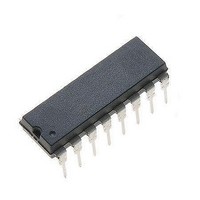
ULN2070B STMicroelectronics, ULN2070B Datasheet - Page 5

ULN2070B
Manufacturer Part Number
ULN2070B
Description
Darlington Transistors DISC BY STM 08/01 DIP-16 QUAD 1.5A DAR
Manufacturer
STMicroelectronics
Specifications of ULN2070B
Configuration
Quad
Transistor Polarity
NPN
Mounting Style
Through Hole
Package / Case
PowerPDIP
Collector- Emitter Voltage Vceo Max
50 V
Maximum Dc Collector Current
1.75 A
Maximum Operating Temperature
+ 85 C
Minimum Operating Temperature
- 20 C
Lead Free Status / RoHS Status
Lead free / RoHS Compliant
MOUNTING INSTRUCTIONS
The R
pins to a suitable copper area of the printed circuit
board (Fig. 12) or to an external heatsink (Fig. 13).
The diagram of Figure 14 shows the maximum dis-
sipable power P
the side " " of two equal square copper areas hav-
ing a thickness of 35
Figure 12 : Example of P.C. Board Area which is
Figure 14 : Maximum Dissipable Power and Junc-
th j-amb
Used as Heatsink.
tion to Ambient Thermal Resistance
vs. Side " ".
can be reduced by soldering the GND
tot
and the R
(1.4 mils).
ULN2064B-ULN2066B-ULN2068B-ULN2070B-ULN2074B-ULN2076B
th j-amb
as a function of
During soldering the pins temperature must not ex-
ceed 260 °C and the soldering time must not be
longer than 12 seconds.
The external heatsink or printed circuit copper area
must be connected to electrical ground.
Figure 13 : External Heatsink Mounting Example.
Figure 15 : Maximum Allowable Power Dissipa-
tion vs. Ambient Temperature.
5/8


