A1360LKTTN-T Allegro Microsystems Inc, A1360LKTTN-T Datasheet - Page 14
A1360LKTTN-T
Manufacturer Part Number
A1360LKTTN-T
Description
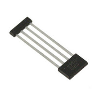
IC,HALL-EFFECT SENSOR,SINGLE-ENDED,BICMOS,SIP,4PIN,PLASTIC
Manufacturer
Allegro Microsystems Inc
Type
Linear - Unipolar, Bipolarr
Datasheet
1.A1360LKTTN-T.pdf
(25 pages)
Specifications of A1360LKTTN-T
Sensing Range
0.7mV/G ~ 1.4mV/G
Voltage - Supply
4.5 V ~ 5.5 V
Current - Supply
12mA
Current - Output (max)
10mA
Output Type
Analog, Ratiometric
Features
Programmable
Operating Temperature
-40°C ~ 150°C
Package / Case
4-SIP
Lead Free Status / RoHS Status
Lead free / RoHS Compliant
Other names
620-1233-2


A1360, A1361,
and A1362
Overview
Programming is accomplished by sending a series of input volt-
age pulses serially through the VOUT pin of the device. A unique
combination of different voltage level pulses controls the internal
programming logic of the device to select a desired programmable
parameter and change its value.
There are three voltage levels that must be taken into account
when programming. These levels are referred to as high,
V
ming pulse levels. A high voltage pulse, V
–V
to a V
The 136x features four modes used during programming: Hold
mode, Try mode, Blow mode, and Lock mode:
• In Hold mode, the value of two programmable parameters may
• In Try mode, the value of a single programmable parameter may
• In Blow mode, the value of a single programmable parameter
• In Lock mode, a device-level fuse is blown, blocking the further
The programming sequence is designed to help prevent the device
from being programmed accidentally; for example, as a result of
noise on the supply line. Any programmable variable power sup-
ply can be used to generate the pulse waveforms, although Allegro
highly recommends using the Allegro Sensor IC Evaluation Kit,
available on the Allegro Web site On-line Store. The manual
be set and measured simultaneously. The parameter values are
stored temporarily, and reset after cycling the supply voltage.
be set and measured. The parameter value is stored temporarily,
and resets after cycling the supply voltage. (Note that other
parameters cannot be accessed simultaneously in this mode.)
may be set permanently by blowing solid-state fuses internal to
the device. Additional parameters may be blown sequentially.
programming of all parameters.
P(HIGH)
P(HIGH)
P(LOW)
, mid, V
–V
–V
P(LOW)
P(MID)
P(MID)
sequence. A mid voltage pulse, V
, and low, V
–V
P(LOW)
sequence.
Adjustable Bandwidth (50 kHz Maximum) and Analog Output
P(LOW)
Low-Noise Programmable Linear Hall Effect Sensor ICs with
. There are two program-
PH
, refers to a V
Programming Guidelines
PM
, refers
P(LOW)
for that kit is available for download free of charge, and provides
additional information on programming these devices.
Definition of Terms
Register One of several sections of the programming logic that
control the bit fields storing the code choices for setting program-
ming modes and programmable parameters.
Bit Field The set of internal fuses controlled by a single register.
Each fuse in a bit field represents a binary digit in the code setting
for that register. The internal logic of the device interprets that
code and applies the result to a programmable parameter of the
device. Individual fuses can be temporarily activated for testing of
the result, or permanently blown.
Key A series of one or more consecutive mid voltage pulses that
indicate by their quantity the register being addressed. The quan-
tity of mid voltage pulses corresponds to the decimal equivalent
of the binary value of the register being addressed. For example,
the LSB of a zone is bit 0 (binary 0), corresponding to register 1,
and indicated by key 1 (decimal 1), a single mid voltage pulse.
Code A series of one or more consecutive mid voltage pulses that
indicate by their quantity the combination of fuses to be activated
or blown in the currently-selected register. The quantity of pulses
in the code corresponds to the decimal equivalent of the binary
value of the bits (links) to be activated or blown. The LSB of a bit
field is bit 0, activated by code 1 (decimal 1), a single mid voltage
pulse.
Addressing Indicating the target register or bit field setting by
incrementing the key or code by means of pulse trains of consecu-
tive mid voltage pulses transmitted through the VOUT pin of the
device. During the addressing process, each parameter can be
measured, before either blowing the fuses to permanently set the
programming code (and parameter value), or cycling the power to
reset the unblown bits.
115 Northeast Cutoff
1.508.853.5000; www.allegromicro.com
Allegro MicroSystems, Inc.
Worcester, Massachusetts 01615-0036 U.S.A.
14
Related parts for A1360LKTTN-T
Image
Part Number
Description
Manufacturer
Datasheet
Request
R

Part Number:
Description:
Manufacturer:
Allegro Micro Systems, Inc.
Datasheet:

Part Number:
Description:
CONN RECEPT CPC 4POS REV SER 1
Manufacturer:
Tyco Electronics
Datasheet:

Part Number:
Description:
IC, HALL EFFECT SENSOR, Linear, SOIC-8
Manufacturer:
Allegro Microsystems Inc
Datasheet:
Part Number:
Description:
IC, HALL EFFECT SENSOR, Linear, SOIC-8
Manufacturer:
Allegro Microsystems Inc
Datasheet:
Part Number:
Description:
IC, HALL EFFECT SENSOR, Linear, SOIC-8
Manufacturer:
Allegro Microsystems Inc
Datasheet:

Part Number:
Description:
IC SWITCH INTERFACE 2CHAN 8-SOIC
Manufacturer:
Allegro Microsystems Inc
Datasheet:

Part Number:
Description:
IC SMOKE DETECTOR ION 16-DIP
Manufacturer:
Allegro Microsystems Inc
Datasheet:
Part Number:
Description:
IC SMOKE DETECTOR ION 16-DIP
Manufacturer:
Allegro Microsystems Inc
Datasheet:
Part Number:
Description:
IC SMOKE DETECTOR ION 16-DIP
Manufacturer:
Allegro Microsystems Inc
Datasheet:
Part Number:
Description:
IC SMOKE DETECTOR PHOTO 16-DIP
Manufacturer:
Allegro Microsystems Inc
Datasheet:
Part Number:
Description:
IC SMOKE DETECTOR ION 16-DIP
Manufacturer:
Allegro Microsystems Inc
Datasheet:
Part Number:
Description:
IC SMOKE DETECTOR PHOTO 16-DIP
Manufacturer:
Allegro Microsystems Inc
Datasheet:
Part Number:
Description:
IC SMOKE DETECTOR PHOTO 16-DIP
Manufacturer:
Allegro Microsystems Inc
Datasheet:
Part Number:
Description:
IC SMOKE DETECTOR ION 16-DIP
Manufacturer:
Allegro Microsystems Inc
Datasheet:
Part Number:
Description:
IC SMOKE DETECTOR PHOTO 16-SOIC
Manufacturer:
Allegro Microsystems Inc
Datasheet: