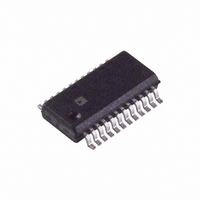
ADA4411-3ARQZ-R7 Analog Devices Inc, ADA4411-3ARQZ-R7 Datasheet - Page 12

ADA4411-3ARQZ-R7
Manufacturer Part Number
ADA4411-3ARQZ-R7
Description
IC,TV/VIDEO CIRCUIT,TV/Video Filter,SSOP,24PIN,PLASTIC
Manufacturer
Analog Devices Inc
Datasheet
1.ADA4411-3ARQZ-RL.pdf
(16 pages)
Specifications of ADA4411-3ARQZ-R7
Applications
2:1 Multiplexer-Amplifier
Output Type
Rail-to-Rail
Number Of Circuits
3
Current - Supply
57mA
Current - Output / Channel
30mA
Voltage - Supply, Single/dual (±)
4.5 V ~ 12 V, ±2.25 V ~ 6 V
Mounting Type
Surface Mount
Package / Case
24-SSOP (0.150", 3.90mm Width)
Lead Free Status / RoHS Status
Lead free / RoHS Compliant
ADA4411-3
Figure 20 and Figure 21 illustrate several ways to use the
LEVEL1 and LEVEL2 inputs.
to generate fully adjustable LEVEL1 and LEVEL2 voltages from
±5 V and single +5 V supplies. These circuits show a general
case, but a more practical approach is to fix one voltage and
vary the other.
a 600 mV output offset voltage in a single-supply application.
Although the LEVEL2 input could simply be connected to
GND, Figure 21 includes bypassed resistive voltage dividers for
each input so that the input levels can be changed, if necessary.
Additionally, many in-circuit testers require that I/O signals not
be tied directly to the supplies or GND. DNP indicates do not
populate.
9.53kΩ
9.53kΩ
9.09kΩ
Figure 21. Flexible Circuits to Set the LEVEL1 and LEVEL2 Inputs to
10kΩ
634Ω
1kΩ
1kΩ
Figure 20. Generating Fully Adjustable Output Offsets
+5V
+5V
–5V
+5V
Obtain a 600 mV Output Offset on a Single Supply
Figure 21 illustrates an effective way to produce
SINGLE SUPPLY
0.1μF
0.1μF
DUAL SUPPLY
0.1μF
LEVEL1
LEVEL1
LEVEL1
Figure 20 shows examples of how
9.53kΩ
9.53kΩ
9.09kΩ
DNP
1kΩ
1kΩ
0Ω
+5V
+5V
–5V
+5V
0.1μF
0.1μF
DNP
LEVEL2
LEVEL2
LEVEL2
Rev. 0 | Page 12 of 16
INPUT AND OUTPUT COUPLING
Inputs to the ADA4411-3 are normally dc-coupled. Ac coupling
the inputs is not recommended; however, if ac coupling is
necessary, suitable circuitry must be provided following the ac
coupling element to provide proper dc level and bias currents at
the ADA4411-3 input stages. The ADA4411-3 outputs can be
either ac- or dc-coupled.
When driving single ac-coupled loads in standard 75 Ω video
distribution systems, 220 μF coupling capacitors are recom-
mended for use on all but the chrominance signal output. Since
the chrominance signal is a narrow-band modulated carrier, it
has no low frequency content and can therefore be coupled with
a 0.1 μF capacitor.
There are two ac coupling options when driving two loads from
one output. One simply uses the same value capacitor on the
second load, while the other is to use a common coupling
capacitor that is at least twice the value used for the single load
(see Figure 22 and Figure 23).
When driving two parallel 150 Ω loads (75 Ω effective load),
the 3 dB bandwidth of the filters typically varies from that of
the filters with a single 150 Ω load. For the 9 MHz and 18 MHz
filters, the typical variation is within ±1.0%; for the 36 MHz
filters, the typical variation is within ±2.5%.
Figure 23. Driving Two AC-Coupled Loads with One Common Coupling Capacitor
Figure 22. Driving Two AC-Coupled Loads with Two Coupling Capacitors
ADA4411-3
ADA4411-3
470μF
75Ω
75Ω
75Ω
75Ω
220μF
220μF
CABLE
CABLE
75Ω
75Ω
CABLE
CABLE
75Ω
75Ω
75Ω
75Ω
75Ω
75Ω


