AD9788-EBZ Analog Devices Inc, AD9788-EBZ Datasheet - Page 29
AD9788-EBZ
Manufacturer Part Number
AD9788-EBZ
Description
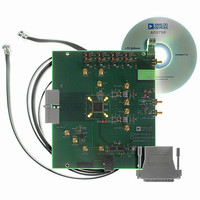
BOARD EVAL FOR AD9788
Manufacturer
Analog Devices Inc
Series
TxDAC®r
Datasheet
1.AD9785BSVZ.pdf
(64 pages)
Specifications of AD9788-EBZ
Design Resources
Powering the AD9788 Using ADP2105 for Increased Efficiency (CN0141)
Number Of Dac's
2
Number Of Bits
16
Outputs And Type
2, Differential
Sampling Rate (per Second)
800M
Data Interface
Serial
Settling Time
22ms
Dac Type
Current
Voltage Supply Source
Analog and Digital
Operating Temperature
-40°C ~ 85°C
Utilized Ic / Part
AD9788
Silicon Manufacturer
Analog Devices
Application Sub Type
DAC
Kit Application Type
Data Converter
Silicon Core Number
AD9788
Kit Contents
Board
Development Tool Type
Hardware - Eval/Demo Board
Lead Free Status / RoHS Status
Lead free / RoHS Compliant


The PLL control (PLLCTL) register comprises three bytes located at Address 0x04. These bits are routed directly to the periphery of the
digital logic. No digital functionality within the main digital block is required.
Table 14. PLL Control (PLLCTL) Register
Address
0x04
The I DAC control register comprises two bytes located at Address 0x05. These bits are routed directly to the periphery of the digital
logic. No digital functionality within the main digital block is required.
Table 15. I DAC Control Register
Address
0x05
[23:21]
[20:16]
[15]
[14:13]
[12:11]
[10:8]
[7:2]
[1:0]
Bit
Bit
[15]
[14]
[13:10]
[9:0]
PLL enable
PLL VCO Divisor [1:0]
PLL Loop Divisor [1:0]
PLL Bias [2:0]
PLL Band Select [5:0]
PLL VCO Drive [1:0]
Name
VCO Control Voltage
[2:0]
PLL Loop Bandwidth
[4:0]
Name
I DAC sleep
I DAC power-down
Reserved
I DAC gain
adjustment
These bits control the signal strength of the VCO output. Set to 11 for optimal performance.
Description
000 to 111, proportional to voltage at VCO, control voltage input (readback only). A value of
011 indicates that the VCO control voltage is centered.
These bits control the bandwidth of the PLL filter. Increasing the value lowers the loop
bandwidth. Set to 01111 for optimal performance.
0: Default. With PLL off, the DAC sample clock is sourced directly by the REFCLK input.
1: With PLL on, the DAC clock is synthesized internally from the REFCLK input via the PLL
clock multiplier. See the Clock Multiplication section for details.
Sets the value of the VCO output divider, which determines the ratio of the VCO output
frequency to the DAC sample clock frequency, f
Sets the value of the DACCLK divider, which determines the ratio of the DAC sample clock
frequency to the REFCLK frequency, f
These bits control the VCO bias current. Set to 011 for optimal performance.
These bits set the operating frequency of the VCO. For further details, refer to Table 35.
0: Default. If the I DAC power-down bit is cleared, the I DAC is active.
Description
0: Default. If the I DAC sleep bit is cleared, the I DAC is active.
1: If the I DAC sleep bit is set, the I DAC is inactive and enters a low power state.
1: If the I DAC power-down bit is set, the I DAC is inactive and enters a low power state.
Reserved for future use.
These bits are the I DAC gain adjustment bits.
00: f
01: f
10: f
11: f
00: f
01: f
10: f
11: f
VCO
VCO
VCO
VCO
DACCLK
DACCLK
DACCLK
DACCLK
/f
/f
/f
/f
DACCLK
DACCLK
DACCLK
DACCLK
/f
/f
/f
/f
Rev. A | Page 29 of 64
REFCLK
REFCLK
REFCLK
REFCLK
= 1
= 2
= 4
= 8
= 2
= 4
= 8
= 16
DACCLK
/f
REFCLK
VCO
.
/f
DACCLK
AD9785/AD9787/AD9788
.
Related parts for AD9788-EBZ
Image
Part Number
Description
Manufacturer
Datasheet
Request
R

Part Number:
Description:
Dual 16B, 1.0 GSPS TxDAC
Manufacturer:
Analog Devices Inc
Datasheet:

Part Number:
Description:
±1.7g Dual-Axis IMEMS Accelerometer Evaluation Board
Manufacturer:
Analog Devices Inc
Datasheet:
Part Number:
Description:
Inertial Sensor Evaluation System
Manufacturer:
Analog Devices Inc
Datasheet:
Part Number:
Description:
Manufacturer:
Analog Devices Inc
Datasheet:
Part Number:
Description:
Manufacturer:
Analog Devices Inc
Datasheet:
Part Number:
Description:
Manufacturer:
Analog Devices Inc
Datasheet:
Part Number:
Description:
Manufacturer:
Analog Devices Inc
Datasheet:
Part Number:
Description:
Manufacturer:
Analog Devices Inc
Datasheet:
Part Number:
Description:
Manufacturer:
Analog Devices Inc
Datasheet:
Part Number:
Description:
Manufacturer:
Analog Devices Inc
Datasheet:
Part Number:
Description:
Manufacturer:
Analog Devices Inc
Datasheet:
Part Number:
Description:
Manufacturer:
Analog Devices Inc
Datasheet:
Part Number:
Description:
Manufacturer:
Analog Devices Inc
Datasheet: