STPS15H100CB STMicroelectronics, STPS15H100CB Datasheet
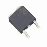
DIODE SCHOTTKY 100V 7.5A DPAK

STPS15H100CB

Manufacturer Part Number
STPS15H100CB
Description
DIODE SCHOTTKY 100V 7.5A DPAK
Manufacturer
STMicroelectronics
Datasheet

Specifications of STPS15H100CB

Voltage - Forward (vf) (max) @ If
800mV @ 7.5A
Current - Reverse Leakage @ Vr
3µA @ 100V
Current - Average Rectified (io) (per Diode)
7.5A
Voltage - Dc Reverse (vr) (max)
100V
Diode Type
Schottky
Speed
Fast Recovery =< 500ns, > 200mA (Io)
Diode Configuration
1 Pair Common Cathode
Mounting Type
Surface Mount
Package / Case
DPak, TO-252 (2 leads+tab), SC-63
Product
Schottky Diodes
Peak Reverse Voltage
100 V
Forward Continuous Current
15 A
Max Surge Current
75 A
Configuration
Dual Common Cathode
Forward Voltage Drop
0.89 V
Maximum Reverse Leakage Current
3 uA
Operating Temperature Range
+ 175 C
Mounting Style
SMD/SMT
Rectifier Type
Schottky Diode
Peak Rep Rev Volt
100V
Avg. Forward Curr (max)
15A
Rev Curr
3uA
Peak Non-repetitive Surge Current (max)
75A
Forward Voltage
0.89V
Operating Temp Range
-65C to 175C
Package Type
DPAK
Operating Temperature Classification
Military
Mounting
Surface Mount
Pin Count
2 +Tab
Lead Free Status / RoHS Status
Lead free / RoHS Compliant
Reverse Recovery Time (trr)
-
Lead Free Status / Rohs Status
Lead free / RoHS Compliant

Available stocks

Company
Part Number
Manufacturer
Quantity
Price
Part Number:
STPS15H100CB
0
Company:
Part Number:
STPS15H100CB
Quantity:
2 400
Part Number:
STPS15H100CB-TR
Manufacturer:
HOLTEK
Quantity:
31 500
Part Number:
STPS15H100CB-TR
Manufacturer:
ST
0
Part Number:
STPS15H100CB-TR
Manufacturer:
ST
Quantity:
180
Part Number:
STPS15H100CB-TR
Manufacturer:
ST
Quantity:
20 000
Company:
Part Number:
STPS15H100CB-TR
Quantity:
10 000
Part Number:
STPS15H100CB-TR,
Manufacturer:
ST
0
Part Number:
STPS15H100CB-TR-S15H100
Manufacturer:
ST
0
Part Number:
STPS15H100CBTR
Manufacturer:
ST
0
Part Number:
STPS15H100CBY-TR
Manufacturer:
TDK
Quantity:
45 000
Part Number:
STPS15H100CBY-TR
Manufacturer:
ST
0
Company:
Part Number:
STPS15H100CBY-TR
Quantity:
10 000
Main product characteristics
Features and Benefits
Description
Dual center tab Schottky rectifier suited for
switched mode power supply and high frequency
DC to DC converters.
Packaged in DPAK and IPAK, this device is
intended for use in high frequency inverters.
Table 1.
1.
June 2006
Symbol
I
Negligible switching losses
Low leakage current
Good trade off between leakage current and
forward voltage drop
Low thermal resistance
Avalanche capability specified
V
F(RMS)
I
P
dV/dt
dPtot
---------------
I
I
F(AV)
T
RRM
dTj
FSM
ARM
RRM
T
stg
j
V
T
<
V
I
j
F
F(AV)
------------------------- -
Rth j a
(max)
(max)
RRM
(
1
Absolute Ratings (limiting values, per diode)
Repetitive peak reverse voltage
RMS forward current
Average forward current
Surge non repetitive forward current
Peak repetitive reverse current
Repetitive peak avalanche power
Storage temperature range
Maximum operating junction temperature
Critical rate of rise of reverse voltage
)
condition to avoid thermal runaway for a diode on its own heatsink
2 x 7.5 A
175° C
0.67 V
100 V
Parameter
High voltage power Schottky rectifier
Rev 4
(1)
T
δ = 0.5
t
t
t
p
p
p
c
= 10 ms sinusoidal
= 2 µs square F= 1 kHz
= 1 µs Tj = 25° C
= 135° C
STPS15H100CB
K
DPAK
Per diode
Per device
A1
A2
A1
STPS15H100C
A2
K
-65 to + 175
STPS15H100CH
10000
Value
6600
100
175
7.5
10
15
75
1
K
IPAK
A1
www.st.com
V/µs
K
Unit
°C
°C
W
V
A
A
A
A
A2
1/8
8

Related parts for STPS15H100CB

STPS15H100CB Summary of contents

Page 1

... Rth j a – June 2006 High voltage power Schottky rectifier 2 x 7.5 A 100 V 175° C 0.67 V STPS15H100CB Parameter T = 135° δ sinusoidal µs square F= 1 kHz µ 25° (1) Rev 4 STPS15H100C ...

Page 2

Characteristics 1 Characteristics Table 2. Thermal resistance Symbol R Junction to case th(j-c) R Coupling th(c) When the diodes 1 and 2 are used simultaneously : ∆ T (diode 1) = P(diode1 Table 3. Static electrical characteristics ...

Page 3

STPS15H100C Figure 1. Conduction losses versus average current PF(av)( δ = 0.2 5 δ = 0.1 4 δ IF(av)( Figure 3. Normalized avalanche power derating versus ...

Page 4

Characteristics Figure 7. Reverse leakage current versus reverse voltage applied (typical values) IR(mA) 1.E+01 Tj=150°C 1.E+00 Tj=125°C Tj=100°C 1.E-01 Tj=75°C 1.E-02 Tj=50°C 1.E-03 Tj=25°C 1.E- Figure 9. Forward voltage drop versus forward current IFM(A) ...

Page 5

STPS15H100C 2 Package Information Epoxy meets UL94,V0 Table 4. DPAK Package mechanical data Figure 11. DPAK Footprint (dimensions in mm) Ref Millimeters Min. A 2.20 A1 0.90 A2 0.03 B 0.64 B2 5.20 C 0.45 C2 0.48 D 6.00 E ...

Page 6

Package Information Table 5. IPAK Package mechanical data 6 STPS15H100C Dimensions Ref. Millimeters Min. Typ. Max. Min. A 2.20 2.40 0.086 A1 ...

Page 7

... STPS15H100C 3 Ordering Information Ordering type STPS15H100CB STPS15H100CB-TR STPS15H100CH 4 Revision History Date Mar-2004 08-Jun-2006 Marking Package S15H100 DPAK S15H100 DPAK S15H100CH IPAK Revision 3 Last issue 4 Reformatted to current standard. Added IPAK. Ordering Information Weight Base qty Delivery mode 0. Tube 0.30 g 2500 Tape andreel ...

Page 8

... Information in this document is provided solely in connection with ST products. STMicroelectronics NV and its subsidiaries (“ST”) reserve the right to make changes, corrections, modifications or improvements, to this document, and the products and services described herein at any time, without notice. All ST products are sold pursuant to ST’s terms and conditions of sale. ...

Related keywords