30CTQ060S Vishay, 30CTQ060S Datasheet - Page 4
30CTQ060S
Manufacturer Part Number
30CTQ060S
Description
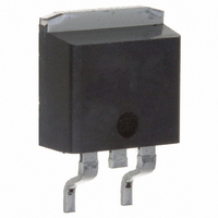
DIODE SCHOTTKY 60V 15A D2PAK
Manufacturer
Vishay
Datasheet
1.30CTQ060STRLPBF.pdf
(9 pages)
Specifications of 30CTQ060S
Voltage - Forward (vf) (max) @ If
860mV @ 15A
Current - Reverse Leakage @ Vr
550µA @ 60V
Current - Average Rectified (io) (per Diode)
15A
Voltage - Dc Reverse (vr) (max)
60V
Diode Type
Schottky
Speed
Fast Recovery =< 500ns, > 200mA (Io)
Diode Configuration
1 Pair Common Cathode
Mounting Type
Surface Mount
Package / Case
D²Pak, TO-263 (2 leads + tab)
Product
Schottky Rectifiers
Peak Reverse Voltage
60 V
Forward Continuous Current
30 A
Max Surge Current
1000 A
Configuration
Dual Common Cathode
Forward Voltage Drop
0.82 V
Maximum Reverse Leakage Current
800 uA
Operating Temperature Range
- 55 C to + 150 C
Mounting Style
SMD/SMT
Lead Free Status / RoHS Status
Contains lead / RoHS non-compliant
Reverse Recovery Time (trr)
-
Lead Free Status / RoHS Status
Contains lead / RoHS non-compliant, Lead free / RoHS Compliant
Other names
*30CTQ060S
VS-30CTQ060S
VS-30CTQ060S
VS30CTQ060S
VS30CTQ060S
VS-30CTQ060S
VS-30CTQ060S
VS30CTQ060S
VS30CTQ060S
Available stocks
Company
Part Number
Manufacturer
Quantity
Price
Company:

Part Number:
30CTQ060S
Manufacturer:
IR
Quantity:
10 000
Company:
Part Number:
30CTQ060SPBF
Manufacturer:
VIR
Quantity:
3 028
Company:
Part Number:
30CTQ060STRLPBF
Manufacturer:
VIR
Quantity:
4 000
Part Number:
30CTQ060STRLPBF
Manufacturer:
VISHAY/威世
Quantity:
20 000


Document Number: 93306
30CTQ... Series
Bulletin PD-20300 rev. D 07/04
(2) Formula used: T
Pd = Forward Power Loss = I
Pd
160
150
140
130
120
110
100
90
80
70
60
REV
Fig. 5 - Max. Allowable Case Temperature
0
= Inverse Power Loss = V
Vs. Average Forward Current (Per Leg)
S quare wave (D = 0.50)
80% Ra ted V a p plied
see note (2)
Average F orward Current - I
CURRENT
MONIT OR
5
C
DUT
= T
R
J
- (Pd + Pd
10
F(AV)
Fig. 7 - Max. Non-Repetitive Surge Current (Per Leg)
REV
R1
15
1000
x V
100
x I
) x R
FM
R
S quare Wave Pulse Duration - t
(1 - D); I
DC
10
Fig. 8 - Unclamped Inductive Test Circuit
@ (I
thJC
R g = 25 ohm
F(AV)
20
F(AV)
;
R
At Any Rated Load Condition
And With Rated V
Following S urge
(A)
IR F P460
@ V
/
D) (see Fig. 6);
L
25
R1
100
= 10 V
RRM
1000
FREE-WHEEL
40HF L40S 02
p
Applied
DIODE
HIGH-S PEED
(microsec)
S WIT CH
14
12
10
10000
Fig. 6 - Forward Power Loss Characteristics
8
6
4
2
0
0
Average Forward Current - I
D = 0.20
D = 0.25
D = 0.33
D = 0.50
D = 0.75
RMS Limit
5
+
(Per Leg)
10
Vd = 25 Volt
www.vishay.com
15
DC
F(AV)
20
(A)
4
25
Related parts for 30CTQ060S
Image
Part Number
Description
Manufacturer
Datasheet
Request
R

Part Number:
Description:
357-036-542-201 CARDEDGE 36POS DL .156 BLK LOPRO
Manufacturer:
Vishay
Datasheet:
Part Number:
Description:
357-036-542-201 CARDEDGE 36POS DL .156 BLK LOPRO
Manufacturer:
Vishay
Datasheet:
Part Number:
Description:
357-036-542-201 CARDEDGE 36POS DL .156 BLK LOPRO
Manufacturer:
Vishay
Datasheet:
Part Number:
Description:
357-036-542-201 CARDEDGE 36POS DL .156 BLK LOPRO
Manufacturer:
Vishay
Datasheet:
Part Number:
Description:
357-036-542-201 CARDEDGE 36POS DL .156 BLK LOPRO
Manufacturer:
Vishay
Datasheet:
Part Number:
Description:
357-036-542-201 CARDEDGE 36POS DL .156 BLK LOPRO
Manufacturer:
Vishay
Datasheet:
Part Number:
Description:
357-036-542-201 CARDEDGE 36POS DL .156 BLK LOPRO
Manufacturer:
Vishay
Datasheet:
Part Number:
Description:
357-036-542-201 CARDEDGE 36POS DL .156 BLK LOPRO
Manufacturer:
Vishay
Datasheet:
Part Number:
Description:
357-036-542-201 CARDEDGE 36POS DL .156 BLK LOPRO
Manufacturer:
Vishay
Datasheet:
Part Number:
Description:
357-036-542-201 CARDEDGE 36POS DL .156 BLK LOPRO
Manufacturer:
Vishay
Datasheet:
Part Number:
Description:
357-036-542-201 CARDEDGE 36POS DL .156 BLK LOPRO
Manufacturer:
Vishay
Datasheet:
Part Number:
Description:
357-036-542-201 CARDEDGE 36POS DL .156 BLK LOPRO
Manufacturer:
Vishay
Datasheet:
Part Number:
Description:
357-036-542-201 CARDEDGE 36POS DL .156 BLK LOPRO
Manufacturer:
Vishay
Datasheet:
Part Number:
Description:
357-036-542-201 CARDEDGE 36POS DL .156 BLK LOPRO
Manufacturer:
Vishay
Datasheet:
Part Number:
Description:
357-036-542-201 CARDEDGE 36POS DL .156 BLK LOPRO
Manufacturer:
Vishay
Datasheet: