STGP20NC60V STMicroelectronics, STGP20NC60V Datasheet - Page 2
STGP20NC60V
Manufacturer Part Number
STGP20NC60V
Description
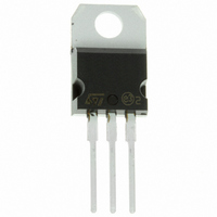
IGBT N-CHAN 60A 600V TO220
Manufacturer
STMicroelectronics
Series
PowerMESH™r
Specifications of STGP20NC60V
Voltage - Collector Emitter Breakdown (max)
600V
Vce(on) (max) @ Vge, Ic
2.5V @ 15V, 20A
Current - Collector (ic) (max)
60A
Power - Max
200W
Input Type
Standard
Mounting Type
Through Hole
Package / Case
TO-220-3 (Straight Leads)
Transistor Type
IGBT
Dc Collector Current
60A
Collector Emitter Voltage Vces
600V
Power Dissipation Pd
200W
Operating Temperature Range
-55°C To +150°C
No. Of Pins
3
Channel Type
N
Configuration
Single
Collector-emitter Voltage
600V
Collector Current (dc) (max)
60A
Gate To Emitter Voltage (max)
±20V
Package Type
TO-220
Pin Count
3 +Tab
Mounting
Through Hole
Operating Temperature (min)
-55C
Operating Temperature (max)
150C
Operating Temperature Classification
Military
Collector- Emitter Voltage Vceo Max
600 V
Collector-emitter Saturation Voltage
2.5 V
Maximum Gate Emitter Voltage
+/- 20 V
Continuous Collector Current At 25 C
60 A
Gate-emitter Leakage Current
+/- 100 nA
Power Dissipation
200 W
Maximum Operating Temperature
+ 150 C
Continuous Collector Current Ic Max
60 A
Minimum Operating Temperature
- 55 C
Mounting Style
Through Hole
Collector Emitter Voltage V(br)ceo
600V
Rohs Compliant
Yes
Lead Free Status / RoHS Status
Lead free / RoHS Compliant
Igbt Type
-
Lead Free Status / Rohs Status
Compliant
Other names
497-4355-5
Available stocks
Company
Part Number
Manufacturer
Quantity
Price
Company:

Part Number:
STGP20NC60V
Manufacturer:
ST
Quantity:
12 500


STGP20NC60V - STGW20NC60V
2/11
Table 3: Absolute Maximum ratings
(1)Pulse width limited by max. junction temperature.
Table 4: Thermal Data
ELECTRICAL CHARACTERISTICS (T
Table 5: Off
Table 6: On
(#) Calculated according to the iterative formula:
I
C
Rthj-case
Rthj-amb
V
V
Symbol
Symbol
Symbol
V
I
BR(CES)
CM
CE(SAT)
V
T
V
P
I
I
V
GE(th)
T
CES
GES
C
T
CES
ECR
TOT
I
I
T
GE
stg
C
C
L
j
(1)
=
------------------------------------------------------------------------------------------------- -
R
THJ C
Collectro-Emitter Breakdown
Voltage
Collector-Emitter Leakage
Current (V
Gate-Emitter Leakage
Current (V
Gate Threshold Voltage
Collector-Emitter Saturation
Voltage
Collector-Emitter Voltage (V
Reverse Battery Protection
Gate-Emitter Voltage
Collector Current (continuous) at 25°C (#)
Collector Current (continuous) at 100°C (#)
Collector Current (pulsed)
Total Dissipation at T
Derating Factor
Storage Temperature
Operating Junction Temperature
Thermal Resistance Junction-case
Thermal Resistance Junction-ambient
Maximum Lead Temperature for Soldering
Purpose (1.6 mm from case, for 10 sec.)
–
T
V
JMAX
CESAT M AX
Parameter
Parameter
CE
CE
–
= 0)
= 0)
T
C
Parameter
(
C
T
C
= 25°C
I
C
)
GS
CASE
= 0)
I
V
Tc=25°C
Tc=125°C
V
V
V
V
Tj= 125°C
C
GE
GE
CE
GE
GE
= 1 mA, V
= V
= 15 V, I
= 15 V, I
=25°C UNLESS OTHERWISE SPECIFIED)
= Max Rating
= ± 20 V , V
Test Conditions
Test Conditions
GE
, I
C
C
C
GE
= 250 µA
TO-220
TO-247
= 20A, Tj= 25°C
= 20A,
= 0
CE
= 0
Min.
– 55 to 150
Min.
Min.
3.75
600
Value
± 20
600
100
200
1.6
20
60
30
Typ.
300
Typ.
Typ.
1.8
1.7
0.625
Max.
62.5
50
± 100
Max.
Max.
5.75
2.5
10
1
Symbol
W/°C
°C/W
°C/W
°C
°C
W
V
V
V
A
A
A
Unit
Unit
mA
µA
nA
V
V
V
V
Related parts for STGP20NC60V
Image
Part Number
Description
Manufacturer
Datasheet
Request
R

Part Number:
Description:
STMicroelectronics [RIPPLE-CARRY BINARY COUNTER/DIVIDERS]
Manufacturer:
STMicroelectronics
Datasheet:
Part Number:
Description:
STMicroelectronics [LIQUID-CRYSTAL DISPLAY DRIVERS]
Manufacturer:
STMicroelectronics
Datasheet:

Part Number:
Description:
BOARD EVAL FOR MEMS SENSORS
Manufacturer:
STMicroelectronics
Datasheet:
Part Number:
Description:
NPN TRANSISTOR POWER MODULE
Manufacturer:
STMicroelectronics
Datasheet:
Part Number:
Description:
TURBOSWITCH ULTRA-FAST HIGH VOLTAGE DIODE
Manufacturer:
STMicroelectronics
Datasheet:
Part Number:
Description:
Manufacturer:
STMicroelectronics
Datasheet:
Part Number:
Description:
DIODE / SCR MODULE
Manufacturer:
STMicroelectronics
Datasheet:
Part Number:
Description:
DIODE / SCR MODULE
Manufacturer:
STMicroelectronics
Datasheet:
Part Number:
Description:
Search -----> STE16N100
Manufacturer:
STMicroelectronics
Datasheet:
Part Number:
Description:
Search ---> STE53NA50
Manufacturer:
STMicroelectronics
Datasheet:
Part Number:
Description:
NPN Transistor Power Module
Manufacturer:
STMicroelectronics
Datasheet:
Part Number:
Description:
DIODE / SCR MODULE
Manufacturer:
STMicroelectronics
Datasheet: