IXGH32N90B2 IXYS, IXGH32N90B2 Datasheet

IGBT 900V 64A TO-247

IXGH32N90B2

Manufacturer Part Number
IXGH32N90B2
Description
IGBT 900V 64A TO-247
Manufacturer
IXYS
Series
HiPerFAST™r
Datasheet

Specifications of IXGH32N90B2

Igbt Type
PT
Voltage - Collector Emitter Breakdown (max)
900V
Vce(on) (max) @ Vge, Ic
2.7V @ 15V, 32A
Current - Collector (ic) (max)
64A
Power - Max
300W
Input Type
Standard
Mounting Type
Through Hole
Package / Case
TO-247
Channel Type
N
Configuration
Single
Collector-emitter Voltage
900V
Collector Current (dc) (max)
64A
Gate To Emitter Voltage (max)
±20V
Package Type
TO-247
Pin Count
3 +Tab
Mounting
Through Hole
Operating Temperature (min)
-55
Operating Temperature (max)
150C
Operating Temperature Classification
Military
Vces, (v)
900
Ic25, Tc=25°c, Igbt, (a)
64
Ic90, Tc=90°c, Igbt, (a)
-
Ic110, Tc=110°c, Igbt, (a)
32
Vce(sat), Max, Tj=25°c, Igbt, (v)
2.7
Tfi, Typ, Tj=25°c, Igbt, (ns)
165
Eoff, Typ, Tj=125°c, Igbt, (mj)
5.25
Rthjc, Max, Igbt, (°c/w)
0.42
If, Tj=110°c, Diode, (a)
-
Rthjc, Max, Diode, (ºc/w)
-
Package Style
TO-247
Lead Free Status / RoHS Status
Lead free / RoHS Compliant

Available stocks

Company
Part Number
Manufacturer
Quantity
Price
Part Number:
IXGH32N90B2
Manufacturer:
IXYS
Quantity:
18 000
Part Number:
IXGH32N90B2D1
Manufacturer:
IXYS
Quantity:
18 000
HiPerFAST
B2-Class High Speed IGBTs
Symbol
V
V
V
V
I
I
I
SSOA
(RBSOA)
P
T
T
T
Maximum lead temperature for soldering
1.6 mm (0.062 in.) from case for 10 s
Plastic body for 10 s
M
Weight
Symbol
V
I
I
V
CM
C25
C110
GES
CES
J
JM
stg
© 2005 IXYS All rights reserved
CGR
GEM
C
GE(th)
CE(sat)
CES
GES
d
Test Conditions
T
T
Continuous
Transient
T
T
T
V
Clamped inductive load @
T
Mounting torque (TO-247)
Test Conditions
I
V
V
V
I
C
C
C
C
C
C
J
J
GE
CE
GE
CE
= 250 μA, V
= I
= 25°C to 150°C
= 25°C to 150°C; R
= 25°C (limited by leads)
= 110°C
= 25°C, 1 ms
= 15 V, T
= 25°C
= V
= 0 V
= 0 V, V
C110
, V
CES
GE
TM
VJ
GE
= 15 V
CE
= 125°C, R
= ±20 V
= V
IGBT
GE
GE
= 1 MΩ
G
Advance Technical Information
= 10 Ω
T
T
T
J
J
J
600V
(T
= 25°C
= 150°C
= 125°C
J
= 25°C, unless otherwise specified)
IXGH 32N90B2
IXGT 32N90B2
TO-247
TO-268
min.
3.0
Characteristic Values
-55 ... +150
-55 ... +150
Maximum Ratings
typ.
2.2
2.1
I
CM
1.13/10Nm/lb.in.
= 64
900
900
200
±20
±30
300
260
150
300
64
32
max.
±100
6
4
750
5.0
2.7
50
nA
°C
μA
μA
°C
°C
°C
°C
W
V
V
V
V
V
V
V
A
A
A
A
g
g
G = Gate,
E = Emitter,
Features
Applications
Advantages
TO-247 (IXGH)
TO-268 (IXGT)
High frequency IGBT
High current handling capability
MOS Gate turn-on
- drive simplicity
PFC circuits
Uninterruptible power supplies (UPS)
Switched-mode and resonant-mode
power supplies
AC motor speed control
DC servo and robot drives
DC choppers
High power density
Very fast switching speeds for high
frequency applications
V
I
V
t
C25
fi typ
G
CES
CE(sat)
C
E
G
C = Collector,
TAB = Collector
E
= 900 V
=
=
= 150 ns
DS99384(12/05)
2.7 V
64 A
C (TAB)
C (TAB)

Related parts for IXGH32N90B2

IXGH32N90B2 Summary of contents

Page 1

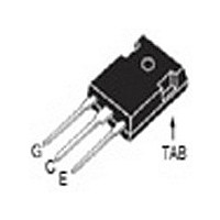
... GE(th CES CE CES ± GES CE(sat) C110 C GE © 2005 IXYS All rights reserved Advance Technical Information IXGH 32N90B2 IXGT 32N90B2 Maximum Ratings 900 = 1 MΩ 900 GE ±20 ± 200 = 10 Ω ≤ 600V 300 -55 ... +150 150 -55 ... +150 300 260 1.13/10Nm/lb.in. TO-247 ...

Page 2

... Note 1: E measured with a DSEP 30-12A ultrafast diode clamp. on Min. Recommended Footprint (Dimensions in inches and mm) IXYS reserves the right to change limits, test conditions, and dimensions. IXYS MOSFETs and IGBTs are covered by 4,835,592 one or more of the following U.S. patents: 4,850,072 4,881,106 ...

Page 3

... Volts CE Fig. 5. Collector-to-Em itter Voltage vs. Gate-to-Em itter voltage 6 5 64A C 32A 5 16A 4.5 4 3.5 3 2 Volts G E © 2005 IXYS All rights reserved º C 240 200 9V 160 120 2.5 3 3.5 4 4.5 º C 1.5 1.4 13V 11V 1.3 9V 1.2 1.1 7V 1.0 ...

Page 4

... C J º º Amperes C Fig. 9. Capacitance 10000 MHz 1000 100 Volts 0.1 0.01 0.1 IXYS reserves the right to change limits, test conditions, and dimensions 100 ies oes res 0 100 Fig. 11. Maxim um Transient Therm al Resistance 1 10 Pulse Width - milliseconds IXGH 32N90B2 IXGT 32N90B2 Fig ...

Page 5

... R - Ohms G Fig. 14. Dependence of Turn-off Energy Loss on Collector Current 16 = 5Ω 15V 125 720V Amperes C Fig. 16. Dependence of Turn-off Energy Loss on Tem perature 16 = 5Ω 15V 720V Degrees Centigrade J © 2005 IXYS All rights reserved 64A 32A 16A º º 64A 32A 16A ...

Page 6

... Sw itching Tim e on Tem perature 400 350 I = 64A, 32A, 16A C 300 250 200 t d(off) R 150 100 Degrees Centigrade J IXYS reserves the right to change limits, test conditions, and dimensions. 400 390 = 15V 40 GE 380 35 370 360 30 350 25 = 32A, 16A 340 20 330 320 ...

Page 7

... IXYS reserves the right to change limits, test conditions, and dimensions without notice. © 2005 IXYS All rights reserved ADVANCE TECHNICAL INFORMATION ...

Related keywords