IRGB20B60PD1PBF International Rectifier, IRGB20B60PD1PBF Datasheet
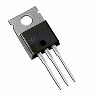
IGBT W/DIODE 600V 40A TO220AB

IRGB20B60PD1PBF

Manufacturer Part Number
IRGB20B60PD1PBF
Description
IGBT W/DIODE 600V 40A TO220AB
Manufacturer
International Rectifier
Type
Warpr
Datasheets

Specifications of IRGB20B60PD1PBF

Igbt Type
NPT
Voltage - Collector Emitter Breakdown (max)
600V
Vce(on) (max) @ Vge, Ic
2.8V @ 15V, 20A
Current - Collector (ic) (max)
40A
Power - Max
215W
Input Type
Standard
Mounting Type
Through Hole
Package / Case
TO-220-3 (Straight Leads)
Capacitance, Gate
1560 pF
Current, Collector
40 A
Energy Rating
195 μJ
Package Type
TO-220AB
Polarity
N-Channel
Power Dissipation
215 W
Resistance, Thermal, Junction To Case
0.58 °C/W
Speed, Switching
60 to 150 kHz
Voltage, Collector To Emitter Shorted
600 V
Voltage, Collector To Emitter, Saturation
2.05 V
Channel Type
N
Configuration
Single
Collector-emitter Voltage
600V
Collector Current (dc) (max)
40A
Gate To Emitter Voltage (max)
±20V
Pin Count
3 +Tab
Mounting
Through Hole
Operating Temperature (min)
-55C
Operating Temperature (max)
150C
Operating Temperature Classification
Military
Transistor Type
IGBT
Dc Collector Current
40A
Collector Emitter Voltage Vces
600V
Power Dissipation Pd
215W
Collector Emitter Voltage V(br)ceo
600V
Operating Temperature Range
-55°C To +150°C
Rohs Compliant
Yes
Package
TO-220AB
Circuit
Co-Pack
Switching
Hard
Switching Speed
WARP 30-150 kHz
Vces (v)
600
Ic @ 25c (a)
40
Ic @ 100c (a)
22
Vce(on)@25c Typ (v)
2.50
Vce(on)@25c Max (v)
2.80
Ets Typ (mj)
0.195
Ets Max (mj)
0.285
Qrr Typ Nc 25c
40
Qrr Max Nc 25c
60
Vf Typ
1.50
Pd @25c (w)
215
Environmental Options
PbF and Leaded
Lead Free Status / RoHS Status
Lead free / RoHS Compliant
Other names
*IRGB20B60PD1PBF

Available stocks

Company
Part Number
Manufacturer
Quantity
Price
Part Number:
IRGB20B60PD1PBF
Manufacturer:
ST
Quantity:
3 000
Part Number:
IRGB20B60PD1PBF
Manufacturer:
IR
Quantity:
20 000
Company:
Part Number:
IRGB20B60PD1PBF M
Quantity:
25 780
WARP2 SERIES IGBT WITH
ULTRAFAST SOFT RECOVERY DIODE
Applications
Features
Benefits
V
I
I
I
I
I
I
I
V
P
P
T
T
R
R
R
R
Absolute Maximum Ratings
Thermal Resistance
C
C
CM
LM
F
F
FRM
J
STG
CES
GE
D
D
θJC
θJC
θCS
θJA
@ T
@ T
@ T
@ T
Telecom and Server SMPS
PFC and ZVS SMPS Circuits
Uninterruptable Power Supplies
Consumer Electronics Power Supplies
Lead-Free
NPT Technology, Positive Temperature Coefficient
Lower V
Lower Parasitic Capacitances
Minimal Tail Current
HEXFRED Ultra Fast Soft-Recovery Co-Pack Diode
Tighter Distribution of Parameters
Higher Reliability
Parallel Operation for Higher Current Applications
Lower Conduction Losses and Switching Losses
Higher Switching Frequency up to 150kHz
@ T
@ T
(IGBT)
(Diode)
C
C
C
C
C
C
= 25°C
= 100°C
= 25°C
= 100°C
= 25°C
= 100°C
CE
(SAT)
Collector-to-Emitter Voltage
Continuous Collector Current
Pulse Collector Current (Ref. Fig. C.T.4)
Clamped Inductive Load Current
Diode Continous Forward Current
Maximum Repetitive Forward Current
Gate-to-Emitter Voltage
Maximum Power Dissipation
Operating Junction and
Storage Temperature Range
Soldering Temperature, for 10 sec.
Mounting Torque, 6-32 or M3 Screw
Thermal Resistance Junction-to-Case-(each IGBT)
Thermal Resistance Junction-to-Case-(each Diode)
Thermal Resistance, Case-to-Sink (flat, greased surface)
Thermal Resistance, Junction-to-Ambient (typical socket mount)
Weight
Parameter
Parameter
e
SMPS IGBT
G
n-channel
IRGB20B60PD1PbF
C
E
Min.
300 (0.063 in. (1.6mm) from case)
–––
–––
–––
–––
–––
10 lbf·in (1.1 N·m)
-55 to +150
2 (0.07)
I
D
Max.
Typ.
0.50
±20
600
215
–––
–––
–––
@ V
40
22
80
80
10
16
86
Equivalent MOSFET
4
R
(FET equivalent) = 20A
V
CE(on)
CE(on)
GE
Parameters
V
CES
= 15V I
typ. = 158mΩ
Max.
typ. = 2.05V
0.58
–––
–––
5.0
80
TO-220AB
= 600V
C
= 13.0A

G
Units
Units
g (oz)
°C/W
C
°C
W
V
A
V
E

Related parts for IRGB20B60PD1PBF

IRGB20B60PD1PBF Summary of contents

Page 1

... Thermal Resistance Junction-to-Case-(each IGBT) θJC Thermal Resistance Junction-to-Case-(each Diode) R (Diode) θJC Thermal Resistance, Case-to-Sink (flat, greased surface) R θCS Thermal Resistance, Junction-to-Ambient (typical socket mount) R θJA Weight SMPS IGBT IRGB20B60PD1PbF n-channel Parameter e Parameter V = 600V CES V typ. = 2.05V CE(on 15V ...

Page 2

... IRGB20B60PD1PbF Electrical Characteristics @ T = 25°C (unless otherwise specified) J Parameter V Collector-to-Emitter Breakdown Voltage (BR)CES ∆V /∆T Temperature Coeff. of Breakdown Voltage (BR)CES J R Internal Gate Resistance G V Collector-to-Emitter Saturation Voltage CE(on) V Gate Threshold Voltage GE(th) ∆V /∆TJ Threshold Voltage temp. coefficient GE(th) gfe ...

Page 3

... J www.irf.com 250 200 150 100 50 100 120 140 160 1000 =15V IRGB20B60PD1PbF 100 120 140 160 T C (°C) Fig Power Dissipation vs. Case Temperature 15V VGE = 12V VGE = 10V VGE = 8.0V VGE = 6. (V) Fig Typ. IGBT Output Characteristics T = -40° 80µ 18V ...

Page 4

... IRGB20B60PD1PbF 450 400 350 25°C 300 125°C 250 200 150 100 (V) Fig Typ. Transfer Characteristics V = 50V 10µ (V) Fig Typical 125°C J 350 300 250 200 150 100 (A) Fig Typ. Energy Loss vs 125° 200µ 390V Diode clamp used: 8ETH06 (See C.T.3) ...

Page 5

... V = 15V 10000 1000 100 400 500 600 700 CE 1.6 1.5 400V 1.4 1.3 1.2 1.1 0.9 0.8 0.7 0 13A IRGB20B60PD1PbF td OFF Ω ) Fig Typ. Switching Time vs 390V 13A Diode clamp used: 8ETH06 (See C.T.3) Cies Coes Cres (V) Fig. 16- Typ. Capacitance vs ...

Page 6

... IRGB20B60PD1PbF 200V 125° 25° 100 di /dt - (A/µs) f 200 V = 200V 125° 25°C J 160 4.0A F 120 100 di /dt - (A/µ 1000 100 f 1000 100 1000 200V 125° 25° 8. 4.0A F 1000 di /dt - (A/µ 200V 125° 25° 8. 4.0A F 100 di /dt - (A/µs) ...

Page 7

... THERMAL RESPONSE ) 0.001 1E-006 1E-005 Fig 23. Maximum Transient Thermal Impedance, Junction-to-Case (IGBT 0.50 0.20 1 0.10 0.05 0.02 0.1 0.01 SINGLE PULSE ( THERMAL RESPONSE ) 0.01 0.001 1E-006 1E-005 Fig. 24. Maximum Transient Thermal Impedance, Junction-to-Case (DIODE) www.irf.com IRGB20B60PD1PbF τ J τ J τ τ τ ...

Page 8

... IRGB20B60PD1PbF 0 1K Fig.C.T.1 - Gate Charge Circuit (turn-off) L PFC diode DUT / DRIVER Rg Fig.C.T.3 - Switching Loss Circuit 8 L VCC 80 V DUT VCC REVERSE RECOVERY CIRCUIT V = 200V R 0.01 Ω 70µH D.U.T. D dif/dt ADJUST IRFP250 G S Fig. C.T.5 - Reverse Recovery Parameter Test Circuit L DUT 480V Rg Fig ...

Page 9

... Fig. WF2 - Typ. Turn-on Loss Waveform RRM di(rec)M/dt 0.75 I RRM di / RRM rr (rec)M b RRM Fig. WF3 - Reverse Recovery Waveform and Definitions IRGB20B60PD1PbF 45 40 TEST CURRENT 90% test current 20 10% test current Eon Loss -5 7.85 7.95 8.05 8.15 Time (µ 125°C using Fig. CT.3 ...

Page 10

... IRGB20B60PD1PbF Dimensions are shown in millimeters (inches) 10.54 (.415) 10.29 (.405) 2.87 (.113) 2.62 (.103) 4 15.24 (.600) 14.84 (.584 14.09 (.555) 13.47 (.530) 1.40 (.055) 3X 1.15 (.045) 2.54 (.100) 2X NOTES: 1 DIMENSIONING & TOLERANCING PER ANSI Y14.5M, 1982. 2 CONTROLLING DIMENSION : INCH "C " ...

Page 11

Note: For the most current drawings please refer to the IR website at: http://www.irf.com/package/ ...

Related keywords