IRG4PH20K International Rectifier, IRG4PH20K Datasheet - Page 2
IRG4PH20K
Manufacturer Part Number
IRG4PH20K
Description
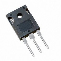
IGBT UFAST 1200V 11A TO-247AC
Manufacturer
International Rectifier
Datasheet
1.IRG4PH20K.pdf
(9 pages)
Specifications of IRG4PH20K
Voltage - Collector Emitter Breakdown (max)
1200V
Vce(on) (max) @ Vge, Ic
4.3V @ 15V, 5A
Current - Collector (ic) (max)
11A
Power - Max
60W
Input Type
Standard
Mounting Type
Through Hole
Package / Case
TO-247-3 (Straight Leads), TO-247AC
Lead Free Status / RoHS Status
Contains lead / RoHS non-compliant
Igbt Type
-
Other names
*IRG4PH20K
Available stocks
Company
Part Number
Manufacturer
Quantity
Price
Company:

Part Number:
IRG4PH20K
Manufacturer:
IR
Quantity:
12 500
Company:
Part Number:
IRG4PH20KD
Manufacturer:
IR
Quantity:
505
Company:
Part Number:
IRG4PH20KD
Manufacturer:
IR
Quantity:
12 500
Company:
Part Number:
IRG4PH20KDPBF
Manufacturer:
ST
Quantity:
50 000


IRG4PH20K
Switching Characteristics @ T
Notes:
Electrical Characteristics @ T
V
V
V
V
g
I
I
Q
Q
Q
t
t
t
t
E
E
E
t
t
t
t
t
E
L
C
C
C
GES
CES
d(on)
d(off)
f
sc
d(on)
d(off)
f
r
r
V
fe
E
(BR)CES
(BR)ECS
GE(th)
V
on
off
CE(ON)
ts
ts
ies
oes
res
g
ge
gc
(BR)CES
2
GE(th)
Repetitive rating; V
max. junction temperature. ( See fig. 13b )
V
(See fig. 13a)
CC
/ T
= 80%(V
/ T
J
J
Parameter
Collector-to-Emitter Breakdown Voltage
Emitter-to-Collector Breakdown Voltage
Temperature Coeff. of Breakdown Voltage
Collector-to-Emitter Saturation Voltage
Gate Threshold Voltage
Temperature Coeff. of Threshold Voltage
Forward Transconductance
Zero Gate Voltage Collector Current
Gate-to-Emitter Leakage Current
Parameter
Total Gate Charge (turn-on)
Gate - Emitter Charge (turn-on)
Gate - Collector Charge (turn-on)
Turn-On Delay Time
Rise Time
Turn-Off Delay Time
Fall Time
Turn-On Switching Loss
Turn-Off Switching Loss
Total Switching Loss
Short Circuit Withstand Time
Turn-On Delay Time
Rise Time
Turn-Off Delay Time
Fall Time
Total Switching Loss
Internal Emitter Inductance
Input Capacitance
Output Capacitance
Reverse Transfer Capacitance
CES
), V
GE
GE
= 20V, pulse width limited by
= 20V, L = 10µH, R
J
J
= 25°C (unless otherwise specified)
= 25°C (unless otherwise specified)
G
=50 ,
1200
Min. Typ. Max. Units
Min. Typ. Max. Units
3.5
2.3
18
—
10
—
—
—
—
—
—
—
—
—
—
—
—
—
—
—
—
—
—
—
—
—
—
—
—
—
—
—
1.13
3.17
4.04
2.84
0.45
0.44
0.89
270
100
620
435
-10
4.4
1.7
8.3
3.5
—
—
—
—
28
12
23
26
93
—
23
28
13
44
—
—
—
Repetitive rating; pulse width limited by maximum
junction temperature.
Pulse width
Pulse width 5.0µs, single shot.
1000
±100
250
140
400
4.3
6.5
2.0
6.6
1.2
—
—
—
—
—
—
43
18
—
—
—
—
—
—
—
—
—
—
—
—
—
—
—
mV/°C V
V/°C
mJ
mJ
µA
nA
nC
nH
pF
ns
µs
V
ns
V
V
S
80µs; duty factor
Energy losses include "tail"
V
ƒ = 1.0MHz
V
V
V
V
V
V
V
V
V
I
V
V
T
I
V
See Fig. 9,10,14
V
T
I
V
Energy losses include "tail"
See Fig. 10,11,14
Measured 5mm from package
V
V
C
C
C
I
I
I
GE
GE
GE
CE
CE
CE
GE
GE
GE
GE
J
J
C
CC
GE
GE
CC
GE
GE
GE
CC
C
C
= 5.0A
=5.0A, V
= 5.0A, V
= 25°C
= 150°C,
= 5.0A
= 11A
= 5.0A , T
= V
= V
= 100 V, I
= 0V, V
= ±20V
= 0V, I
= 0V, I
= 0V, I
= 0V, V
= 0V, V
= 15V
= 0V
= 400V
= 15V, R
= 720V, T
= 15V, R
= 15V, R
= 30V
GE
GE
Conditions
Conditions
, I
, I
C
C
C
CE
C
C
CE
CE
CC
= 250µA
= 1.0A
= 2.5mA
CC
J
= 250µA
= 1mA
G
G
G
C
= 1200V
= 150°C
= 10V, T
= 1200V, T
J
= 960V
= 960
= 50
= 50
= 50
= 5.0A
= 125°C
0.1%.
See Fig.8
See Fig. 7
J
www.irf.com
= 25°C
V
See Fig.2, 5
J
GE
= 150°C
= 15V
Related parts for IRG4PH20K
Image
Part Number
Description
Manufacturer
Datasheet
Request
R

Part Number:
Description:
SCHOTTKY RECTIFIER
Manufacturer:
International Rectifier Corp.
Datasheet:
Part Number:
Description:
SCHOTTKY RECTIFIER
Manufacturer:
International Rectifier Corp.
Datasheet:
Part Number:
Description:
SCHOTTKY RECTIFIER
Manufacturer:
International Rectifier Corp.
Datasheet:
Part Number:
Description:
SCHOTTKY RECTIFIER
Manufacturer:
International Rectifier Corp.
Datasheet:
Part Number:
Description:
SCHOTTKY RECTIFIER
Manufacturer:
International Rectifier Corp.
Datasheet:
Part Number:
Description:
SCHOTTKY RECTIFIER
Manufacturer:
International Rectifier Corp.
Datasheet:
Part Number:
Description:
SCHOTTKY RECTIFIER
Manufacturer:
International Rectifier Corp.
Datasheet:
Part Number:
Description:
SCHOTTKY RECTIFIER
Manufacturer:
International Rectifier Corp.
Datasheet:
Part Number:
Description:
SCHOTTKY RECTIFIER
Manufacturer:
International Rectifier Corp.
Datasheet:
Part Number:
Description:
SCHOTTKY RECTIFIER
Manufacturer:
International Rectifier Corp.
Datasheet:
Part Number:
Description:
SCHOTTKY RECTIFIER
Manufacturer:
International Rectifier Corp.
Datasheet:
Part Number:
Description:
SCHOTTKY RECTIFIER
Manufacturer:
International Rectifier Corp.
Datasheet:
Part Number:
Description:
SCHOTTKY RECTIFIER
Manufacturer:
International Rectifier Corp.
Datasheet:
Part Number:
Description:
SCHOTTKY RECTIFIER
Manufacturer:
International Rectifier Corp.
Datasheet:
Part Number:
Description:
SCHOTTKY RECTIFIER
Manufacturer:
International Rectifier Corp.
Datasheet: