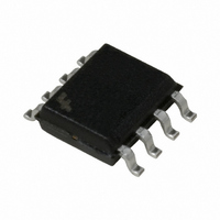
HUFA76404DK8T Fairchild Semiconductor, HUFA76404DK8T Datasheet

HUFA76404DK8T
Specifications of HUFA76404DK8T
Available stocks
Related parts for HUFA76404DK8T
HUFA76404DK8T Summary of contents
Page 1
... G Qualified to AEC Q101 Branding Dash SO-8 ©2005 Fairchild Semiconductor Corporation HUFA76404DK8T Rev. B Applications = 3.2A Motor / Body Load Control D ABS Systems Powertrain Management Injection Systems DC-DC converters and Off-line UPS Distributed Power Architectures and VRMs Primary Switch for 12V and 24V systems ...
Page 2
... Reverse Transfer Capacitance RSS R Gate Resistance G Q Total Gate Charge at 5V g(tot) Q Threshold Gate Charge g(TH) Q Gate to Source Gate Charge gs Q Gate Charge Threshold to Plateau gs2 Q Gate to Drain “Miller” Charge gd HUFA76404DK8T Rev 25°C unless otherwise noted A Parameter 10V C/W) θ 5V C/W) θ ...
Page 3
... This product has been designed to meet the extreme test conditions and environment demanded by the automotive industry. For a copy of the requirements, see AEC Q101 at: http://www.aecouncil.com/ All Fairchild Semiconductor products are manufactured, assembled and tested under ISO9000 and QS9000 quality systems HUFA76404DK8T Rev 10V) ...
Page 4
... Figure 3. Normalized Maximum Transient Thermal Impedance 200 TRANSCONDUCTANCE 100 MAY LIMIT CURRENT IN THIS REGION 10V HUFA76404DK8T Rev 25°C unless otherwise noted 100 125 150 Figure 2. Maximum Continuous Drain Current vs SINGLE PULSE - RECTANGULAR PULSE DURATION ( PULSE WIDTH (s) Figure 4 ...
Page 5
... DUTY CYCLE = 0.5% MAX 180 160 I = 3.6A D 140 120 100 GATE TO SOURCE VOLTAGE (V) GS Figure 9. Drain to Source On Resistance vs Gate Voltage and Drain Current HUFA76404DK8T Rev 25°C unless otherwise noted A 10 100µs STARTING T 1ms 10ms ≠ 100 0.01 Figure 6. Unclamped Inductive Switching ...
Page 6
... Junction Temperature 1000 100 = C C RSS GD ≅ OSS 0V 1MHz DRAIN TO SOURCE VOLTAGE (V) DS Figure 13. Capacitance vs Drain to Source Voltage HUFA76404DK8T Rev 25°C unless otherwise noted A 1 250µ 1.1 1.0 0.9 80 120 160 - Figure 12. Normalized Drain to Source Breakdown Voltage vs Junction Temperature ...
Page 7
... Figure 22. Thermal Impedance vs Mounting Pad Area HUFA76404DK8T Rev and the maximum transient thermal impedance curve. JM Thermal resistances corresponding to other copper areas , can be obtained from Figure calculation using application’s ambient o Equation 2. The area, in square inches is the top copper ...
Page 8
... Test Circuits and Waveforms VARY t TO OBTAIN P R REQUIRED PEAK Figure 15. Unclamped Energy Test Circuit g(REF) Figure 17. Gate Charge Test Circuit Figure 19. Switching Time Test Circuit HUFA76404DK8T Rev DUT 0.01Ω Figure 16. Unclamped Energy Waveforms gs2 DUT g(REF) 0 Figure 18. Gate Charge Waveforms ...
Page 9
... PSPICE Electrical Model .SUBCKT HUFA76404DK8T 3.8e- 3.8e-10 Cin 6 8 2.6e-10 Dbody 7 5 DbodyMOD Dbreak 5 11 DbreakMOD Dplcap 10 5 DplcapMOD Ebreak 62.5 Eds Egs Esg Evthres Evtemp GATE Lgate 1 9 2.22e-9 Ldrain 2 5 1.0e-9 Lsource 3 7 0.93e-9 RLgate 1 9 22.2 RLdrain RLsource 3 7 9.3 ...
Page 10
... HUFA76404DK8T Rev. B DPLCAP RSLC2 - RDRAIN 6 ESG ...
Page 11
... COMPONENT 0.02 in CTHERM6 9.0e-1 CTHERM7 4.0e-1 CTHERM8 1.4 RTHERM6 39 RTHERM7 42 RTHERM8 48 HUFA76404DK8T Rev. B RTHERM1 RTHERM2 RTHERM3 RTHERM4 RTHERM5 RTHERM6 RTHERM7 RTHERM8 Table 1. Thermal Models 2 2 0.14 in 0.257 in 1.3e-1 1.5e-1 6.0e-1 4.5e-1 2.5 2.2 ...
Page 12
... PRODUCT STATUS DEFINITIONS Definition of Terms Datasheet Identification Advance Information Preliminary No Identification Needed Obsolete HUFA76404DK8T Rev. B ImpliedDisconnect™ POP™ IntelliMAX™ Power247™ ISOPLANAR™ PowerEdge™ LittleFET™ PowerSaver™ ...


