FDZ2553NZ Fairchild Semiconductor, FDZ2553NZ Datasheet

MOSFET N-CH 20V 9.6A BGA

FDZ2553NZ

Manufacturer Part Number
FDZ2553NZ
Description
MOSFET N-CH 20V 9.6A BGA
Manufacturer
Fairchild Semiconductor
Series
PowerTrench®r
Datasheet

Specifications of FDZ2553NZ

Fet Type
2 N-Channel (Dual)
Fet Feature
Logic Level Gate
Rds On (max) @ Id, Vgs
14 mOhm @ 9.6A, 4.5V
Drain To Source Voltage (vdss)
20V
Current - Continuous Drain (id) @ 25° C
9.6A
Vgs(th) (max) @ Id
1.5V @ 250µA
Gate Charge (qg) @ Vgs
18nC @ 5V
Input Capacitance (ciss) @ Vds
1240pF @ 10V
Power - Max
2.1W
Mounting Type
Surface Mount
Package / Case
12-BGA (18 pos)
Configuration
Dual Common Drain
Transistor Polarity
N-Channel
Resistance Drain-source Rds (on)
0.012 Ohms
Forward Transconductance Gfs (max / Min)
45 S
Drain-source Breakdown Voltage
20 V
Gate-source Breakdown Voltage
+/- 12 V
Continuous Drain Current
9.6 A
Power Dissipation
2.1 W
Maximum Operating Temperature
+ 150 C
Mounting Style
SMD/SMT
Minimum Operating Temperature
- 55 C
Lead Free Status / RoHS Status
Lead free / RoHS Compliant

Available stocks

Company
Part Number
Manufacturer
Quantity
Price
Part Number:
FDZ2553NZ
Manufacturer:
ZETEX
Quantity:
46
Part Number:
FDZ2553NZ
Manufacturer:
Fairchild Semiconductor
Quantity:
10 000
FDZ2553NZ
General Description
Combining
PowerTrench
packaging, the FDZ2553N minimizes both PCB space
and R
embodies a breakthrough in packaging technology
which enables the device to combine excellent thermal
transfer characteristics, high current handling capability,
ultra-low profile packaging, low gate charge, and low
R
Applications
Monolithic Common Drain N-Channel 2.5V Specified PowerTrench BGA MOSFET
2003 Fairchild Semiconductor Corporation
DS(ON)
Absolute Maximum Ratings
Symbol
V
V
I
P
T
Thermal Characteristics
R
R
R
Package Marking and Ordering Information
D
Battery management
Load switch
Battery protection
D
J
DSS
GSS
, T
JA
JB
J C
Device Marking
Pin 1
STG
.
DS(ON)
2553NZ
.
Fairchild’s
Bottom
Drain-Source Voltage
Gate-Source Voltage
Drain Current
Power Dissipation (Steady State)
Operating and Storage Junction Temperature Range
Thermal Resistance, Junction-to-Ambient
Thermal Resistance, Junction-to-Ball
Thermal Resistance, Junction-to-Case
process
This common drain BGA MOSFET
D
G
G
D
S
S
D
S
S
S
S
D
D
S
S
S
S
D
advanced
with
Q2
Q1
– Continuous
– Pulsed
FDZ2553NZ
state-of-the-art
Parameter
Device
2.5V
Pin 1
specified
T
A
=25
BGA
o
Top
C unless other wise noted
Reel Size
7’’
(Note 1a)
(Note 1a)
(Note 1a)
(Note 1)
(Note 1)
Features
9.6 A, 20 V.
Occupies only 0.10 cm
1/3 the area of SO-8.
Ultra-thin package: less than 0.70 mm height when
mounted to PCB.
ESD protection diode (note 3)
Outstanding thermal transfer characteristics:
significantly better than SO-8.
Ultra-low Q
High power and current handling capability
g
x R
Tape width
R
R
DS(ON)
–55 to +150
12mm
DS(ON)
DS(ON)
Ratings
9.6
2.1
6.3
0.6
20
20
60
12
figure-of-merit
= 14 m
= 20 m @ V
2
of PCB area:
@ V
GS
GS
FDZ2553NZ Rev C (W)
July 2003
= 2.5 V
= 4.5 V
3000 units
Quantity
Units
C/W
W
V
V
A
C

Related parts for FDZ2553NZ

FDZ2553NZ Summary of contents

Page 1

... C unless other wise noted A (Note 1a) (Note 1a) (Note 1a) (Note 1) (Note 1) Reel Size 7’’ July 2003 4.5 V DS(ON 2.5 V DS(ON PCB area figure-of-merit g DS(ON) Ratings Units 9 2.1 W –55 to +150 C 60 C/W 6.3 0.6 Tape width Quantity 12mm 3000 units FDZ2553NZ Rev C (W) ...

Page 2

... GS GEN 9 1.7 A (Note 9.6A 100 A/µ the thermal reference point for the case is defined as the top surface of the JC is determined by the user's board design. JA Typ Max Units mV 0.6 0.9 1.5 V –0.3 mV 1240 pF 320 pF 170 pF 2 1.7 A 0.7 1 FDZ2553NZ Rev C (W) ...

Page 3

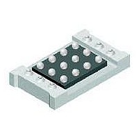
... Dimensional Outline and Pad Layout FDZ2553NZ Rev C (W) ...

Page 4

... C 0.01 0.001 0.0001 2 2.5 0 Figure 6. Body Diode Forward Voltage Variation with Source Current and Temperature. = 2.5V 3.0V 3.5V 4.0V 4. DRAIN CURRENT ( =4 125 GATE TO SOURCE VOLTAGE (V) GS Gate-to-Source Voltage 125 -55 C 0.2 0.4 0.6 0 BODY DIODE FORWARD VOLTAGE (V) SD FDZ2553NZ Rev C ( ...

Page 5

... Figure 8. Capacitance Characteristics. 50 1ms 40 10ms 100 0.01 Figure 10. Single Pulse Maximum 0 TIME (sec 1MHz iss C oss DRAIN TO SOURCE VOLTAGE ( SINGLE PULSE R = 108°C 25° 100 t , TIME (sec) 1 Power Dissipation. R ( 108 °C/W JA P(pk ( Duty Cycle 100 1000 FDZ2553NZ Rev C (W) 20 1000 ...

Page 6

... TRADEMARKS The following are registered and unregistered trademarks Fairchild Semiconductor owns or is authorized to use and is not intended exhaustive list of all such trademarks. ACEx™ FACT™ ActiveArray™ FACT Quiet Series™ Bottomless™ FAST CoolFET™ FASTr™ CROSSVOLT™ ...

Related keywords