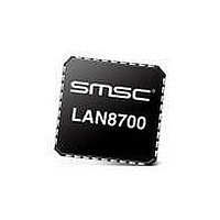
LAN8700IC-AEZG-TR SMSC, LAN8700IC-AEZG-TR Datasheet - Page 17

LAN8700IC-AEZG-TR
Manufacturer Part Number
LAN8700IC-AEZG-TR
Description
Ethernet ICs Hi Perform Ethernet PHY
Manufacturer
SMSC
Type
MII/RMII Ethernet Transceiverr
Datasheet
1.LAN8700C-AEZG.pdf
(80 pages)
Specifications of LAN8700IC-AEZG-TR
Ethernet Connection Type
10 Base-T, 100 Base-TX
Minimum Operating Temperature
0 C
Mounting Style
SMD/SMT
Product
Ethernet Transceivers
Number Of Transceivers
1
Standard Supported
802.3ab
Data Rate
10 Mbps, 100 Mbps
Supply Voltage (max)
3.3 V
Supply Voltage (min)
1.8 V
Supply Current (max)
39 mA, 81.6 mA
Maximum Operating Temperature
+ 70 C
Package / Case
QFN-36
Lead Free Status / RoHS Status
Lead free / RoHS Compliant
Available stocks
Company
Part Number
Manufacturer
Quantity
Price
Part Number:
LAN8700IC-AEZG-TR
Manufacturer:
MICROCHIP/微芯
Quantity:
20 000
±15kV ESD Protected MII/RMII 10/100 Ethernet Transceiver with HP Auto-MDIX Support and flexPWR
Datasheet
SMSC LAN8700/LAN8700i
SIGNAL NAME
SIGNAL NAME
SIGNAL NAME
VDD_CORE
VDDA3.3
EXRES1
VDD33
VDDIO
VSS
RXN
TXN
RXP
TXP
POWER
POWER
POWER
POWER
POWER
TYPE
TYPE
TYPE
AO
AO
Table 3.6 10/100 Line Interface
AI
AI
AI
Table 3.7 Analog References
Table 3.8 Power Signals
DATASHEET
Transmit Data Positive: 100Base-TX or 10Base-T differential
transmit outputs to magnetics.
Transmit Data Negative: 100Base-TX or 10Base-T differential
transmit outputs to magnetics.
Receive Data Positive: 100Base-TX or 10Base-T differential
receive inputs from magnetics.
Receive Data Negative: 100Base-TX or 10Base-T differential
receive inputs from magnetics.
Connects to reference resistor of value 12.4K-Ohm, 1%
connected as described in the Analog Layout Guidelines. The
nominal voltage is 1.2V and therefore the resistor will dissipate
approximately 1mW of power.
+1.6V to +3.6V Variable I/O Pad Power
+3.3V Core Regulator Input.
+3.3V Analog Power
+1.8V (Core voltage) - 1.8V for digital circuitry on chip. Supplied
by the on-chip regulator unless configured for regulator off
mode using the RX_CLK/REGOFF pin. Place a 0.1uF capacitor
near this pin and connect the capacitor from this pin to ground.
When using the on-chip regulator, place a 4.7uF ±20%
capacitor with ESR < 1ohm near this pin and connect the
capacitor from this pin to ground. X5R or X7R ceramic
capacitors are recommended since they exhibit an ESR lower
than 0.1ohm at frequencies greater than 10kHz.
Exposed Ground Flag. The flag must be connected to the
ground plane with an array of vias as described in the Analog
Layout Guidelines
®
17
Technology in a Small Footprint
DESCRIPTION
DESCRIPTION
DESCRIPTION
Revision 2.2 (12-04-09)


