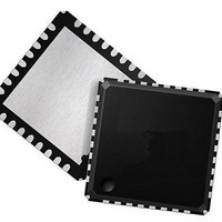
LAN88710AM SMSC, LAN88710AM Datasheet - Page 42

LAN88710AM
Manufacturer Part Number
LAN88710AM
Description
Ethernet ICs MII/RMII 10/100 Automot Transceiver
Manufacturer
SMSC
Datasheet
1.LAN88710BM_SAMPLES.pdf
(80 pages)
Specifications of LAN88710AM
Ethernet Connection Type
10BASE-T, 100BASE-TX
Minimum Operating Temperature
- 40 C
Mounting Style
SMD/SMT
Product
Ethernet Transceivers
Standard Supported
IEEE802.3, IEEE802.3u
Supply Voltage (max)
3.6 V
Supply Voltage (min)
1.6 V
Maximum Operating Temperature
+ 85 C
Package / Case
QFN-32
Lead Free Status / RoHS Status
Lead free / RoHS Compliant
Revision 1.1 (05-26-10)
3.8.1.2
3.8.2
3.8.3
3.8.3.1
nINTSEL and LED2 Polarity Selection
The nINTSEL configuration strap is shared with the LED2 pin. The LED2 output will automatically
change polarity based on the presence of an external pull-down resistor. If the LED2 pin is pulled high
to VDD2A to select a logical high for nINTSEL, then the LED2 output will be active low. If the LED2
pin is pulled low by an external pull-down resistor to select a logical low for nINTSEL, the LED2 output
will then be an active high output.
Note: Refer to
Variable Voltage I/O
The device’s digital I/O pins are variable voltage, allowing them to take advantage of low power
savings from shrinking technologies. These pins can operate from a low I/O voltage of +1.62 V up to
+3.6 V. The applied I/O voltage must maintain its value with a tolerance of ±10%. Varying the voltage
up or down after the transceiver has completed power-on reset can cause errors in the transceiver
operation. Refer to
Note: Input signals must not be driven high before power is applied to the device.
Power-Down Modes
There are two device power-down modes: General Power-Down Mode and Energy Detect Power-
Down Mode. These modes are described in the following subsections.
General Power-Down
This power-down mode is controlled via the
mode, the entire transceiver (except the management interface) is powered-down and remains in this
mode as long as the
powers up and is automatically reset.
LED output = Active Low
VDD2A
information on the nINTSEL configuration strap.
nINTSEL = 1
~270
Ω
LED2/nINTSEL
Section 3.7.5, "nINTSEL: nINT/TXER/TXD4 Configuration," on page 40
Figure 3.6 LED2/nINTSEL Polarity Configuration
Chapter 5, "Operational Characteristics," on page 65
Power Down
Small Footprint MII/RMII 10/100 Ethernet Transceiver for Automotive Applications
Figure 3.6
DATASHEET
bit is “1”. When the
42
details the LED2 polarity for each nINTSEL configuration.
LED output = Active High
Power Down
10K
nINTSEL = 0
Power Down
bit of the
~270
Ω
LED2/nINTSEL
SMSC LAN88710AM/LAN88710BM
Basic Control
bit is cleared, the transceiver
for additional information.
Register. In this
for additional
Datasheet


