MINISPL Neutrik, MINISPL Datasheet - Page 2
MINISPL
Manufacturer Part Number
MINISPL
Description
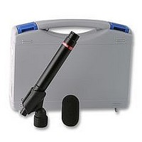
MICROPHONE, SOUND LEVEL
Manufacturer
Neutrik
Datasheet
1.MINISPL.pdf
(2 pages)
Specifications of MINISPL
Svhc
No SVHC (18-Jun-2010)
Lead Free Status / RoHS Status
Lead free / RoHS Compliant


H
• To insert the battery, press the push-pin in and slide the
• Insert one 1.5 V AA size battery according to drawing
• Close the MiniSPL. Turn the sleeve so that it is locked by
N
To avoid any problems during the operation of the
instrument, follow the rules listed below:
• Use the instrument for the intended purpose only.
• Never connect the instrument to a high voltage output
• Do not disassemble the instrument.
• Never use the instrument in a wet environment.
• Remove the batteries as soon as they are flat or if the
• The use of rechargeable NiCd- or NiMH-batteries is
• Note the correct polarity of the inserted battery.
• We recommend to calibrate the MiniSPL in yearly intervals
sleeve off.
below. The polarity is marked on the sticker inside.
Note:
the push-pin.
such as a power amplifier, mains power plug, etc.
instrument is not intended to be used for a longer period
of time.
causing shorter battery lifetime than specified.
to fulfill the specified sensitivity.
ow to insert the battery
otes & Warnings
2
The MiniSPL does not operate without
the battery.
Push-pin
1
Calibration-sticker
M
• Connect the MiniSPL to the Minilyzer ML1.
• Approximately ten seconds later the Status-LED will
• An empty battery will be indicated by the non-flashing
• Simply unplug the MiniSPL after completed operation.
M
The MiniSPL may be operated as a stand-alone microphone
e.g. connected to a balanced audio-line, a microphone-
input or a sound-card.
Note: Follow the specified load condition to achieve the
flat frequency response. Phantom power causes a lower
load condition, so make sure to switch it off.
At inputs with high DC-input resistance you may find the
MiniSPL not switching on or the delay-time until switching
on may be too long. In this case you have to build up an
adapter according to the below circuit diagram. Please note
that both resistance ’’R’’ should be of equal values within
1% tolerance for good signal balancing.
At unbalanced inputs use pin 1 and 2. Pin 3 shall not be
connected. In this case the sensitivity will be halved.
connect
MiniSPL
start to flash periodically indicating that the MiniSPL
has switched on.
Status-LED.
Thus the Status-LED will stop flashing, indicating it is
switched off.
iniSPL with Minilyzer ML1
iniSPL as stand-alone mic
Life
Ground
Return
2
1
3
R
R = 10 kOhm .. 100 kOhm
connect
audio-input
T
Microphone Type
Sensitivity
Frequency Response
Peak Acoustic Input
Noise
Load Conditions
Power Supply
Dimensions
Weight
Temperature
Humidity
Conforms to the
Normative Standards
echnical Data MiniSPL
1/2”, omni-directional,
pre-polarized condenser,
free field transducer
(20 ±2) mV/Pa,
(-34 ±1) dBV/Pa @ 1 kHz, 20°C
+0.05 dB
balanced out
acc. to IEC60651, Type 2,
tolerance curve is shown on
individual calibration certificate
130 dB
32 dB
20 - 200 kOhm balanced,
to achieve this always switch
PHANTOM POWER off.
1x AA battery 1.5 V, battery
lifetime typical 300 hrs,
no phantom power supply,
phantom power resistant
O 22 x 180 mm, O 0.87” x 7”
100 g ( 3.5 oz ) incl. battery
0° to +45° C (32° to 113° F)
< 90 % R.H., non condensing
EMC-Directives:
89/336, 92/31, 93/68
Harmonized Standards:
EN 61326-1
/
SPL
SPL
, A-weighted
SPL
@ 1 kHz
/ °C,
/
Related parts for MINISPL
Image
Part Number
Description
Manufacturer
Datasheet
Request
R


Part Number:
Description:
XLR Connectors 5P MALE TINY CABLE NICKEL HOUSING REAN
Manufacturer:
Neutrik

Part Number:
Description:
XLR Connectors 5P FEMALE TINY CABLE BLK HSG Au CONT REAN
Manufacturer:
Neutrik
Part Number:
Description:
XLR Connectors 5P MALE TINY CABLE Ni HSNG Au CONT REAN
Manufacturer:
Neutrik
Part Number:
Description:
XLR Connectors 5P FEMALE TINY CABLE BLK HSG Au CONT REAN
Manufacturer:
Neutrik