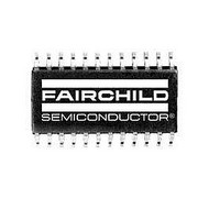
ML6427CS Fairchild Semiconductor, ML6427CS Datasheet - Page 3

ML6427CS
Manufacturer Part Number
ML6427CS
Description
Video ICs Cable Driver/Filter 75Ohm Quad Video
Manufacturer
Fairchild Semiconductor
Type
Provide DC coupled outputs for certain applicationsr
Specifications of ML6427CS
Operating Supply Voltage
5 V
Maximum Operating Temperature
70 C
Package / Case
SOIC-24
Minimum Operating Temperature
0 C
Mounting Style
SMD/SMT
Lead Free Status / RoHS Status
Lead free / RoHS Compliant
Other names
ML6427CS_NL
Available stocks
Company
Part Number
Manufacturer
Quantity
Price
Part Number:
ML6427CS
Manufacturer:
ML
Quantity:
20 000
PIN DESCRIPTION
PIN
10 G
11 B
1
3
4
5
6
7
8
9
2
CV
CV
R
R
A/B MUX
GND
V
G
NAME
CV
IN
IN
IN
CC
IN
IN
INF
INF
A/Y4
B / Y5
A/C1
A/Y6
B/Y7
INU
A/Y2
B/Y3
/Y1
FUNCTION
Logic input pin to select between
Bank <A> or <B> of the CV, RGB,
or Y/C inputs. Internally pulled high.
Unfiltered analog composite video
or luma video input. Internally
pulled high. A composite or luma or
green signal must be present on
either the CV
Y3 input to provide necessary sync
signals to other channels (R, G, B, Y,
C). Otherwise, sync must be
provided at SYNCIN. For RGB
applications the green channel with
sync can be used as an input to this
pin (see RGB Applications section).
Filtered analog composite video or
luma video input for Bank <A>.
Note that SYNC is stripped from this
signal for the other channels. A
composite or luma or green signal
must be present on either the
CV
to provide necessary sync signals to
other channels (R, G, B, Y, C).
Otherwise, sync must be provided
at SYNCIN. For RGB applications
the green channel with sync can be
used as an input to this pin (see
RGB Applications section).
Filtered analog composite video or
luma video input for Bank <B>.
Note that SYNC is stripped from this
signal for the other channels.
Analog ground
Analog 5V supply
Filtered analog RED video or luma
video input for Bank <A>
Filtered analog RED video or luma
video input for Bank <B>
Filtered analog GREEN video or
luma video input for Bank <A>
Filtered analog GREEN video or
luma video input for Bank <B>
Filtered analog BLUE video or
chroma video input for Bank <A>
INF
A/Y2 or the CV
INF
A/Y2 or the CV
INF
B/Y3 input
INF
B/
PIN
12 B
13 SWAP CVF
14 SWAP CVU
15 B
16 G
17 V
18 R
19 GNDO
20 CV
21 CV
22 V
23 SYNCIN
24 SYNCOUT
NAME
IN
OUT
OUT
CCO
CCO
OUT
OUT
OUT
B/C2
/C
/Y
RGB
CV
/Y
1/Y
2/Y
OUT
OUT
OUT
OUT
OUT
C
D
A Composite video output for channel
B Composite video output for channel
FUNCTION
Filtered analog BLUE video or
chroma video input for Bank <B>
Logic input pin to select whether
the outputs of CV
CV
unfiltered CV sources. See Table 1.
Internally pulled low.
Logic input pin to select whether
the outputs of CV
CV
unfiltered CV sources. See Table 1.
Internally pulled low.
Analog BLUE video output or
chroma output from either B
or B
Analog GREEN video output or
luma output from either G
G
5V power supply for output buffers
of the RGB drivers
Analog RED video output or luma
output from either R
Y5
Ground for output buffers
2 or luma output.
1 or luma output.
5V power supply for output buffers
of the CV drivers.
Input for an external H-sync logic
signal for filtered channels. TTL or
CMOS. For normal operation
SYNCOUT is connected to
SYNCIN.
Logic output for H-sync detect for
CV
CMOS. For normal operation
SYNCOUT is connected to
SYNCIN.
IN
OUT
OUT
INF
B/Y7
IN
A/Y2 or CV
B/C2
2/Y
2/Y
OUT
OUT
B are from filtered or
B are from filtered or
OUT
OUT
INF
IN
B/Y3. TTL or
ML6427
1/Y
1/Y
A/Y4 or R
OUT
OUT
IN
A/Y6 or
IN
A and
A and
A/C1
IN
B/
3


